PCB Assembly
Julia Wu - Senior Sales Engineer at NextPCB.com

 NextPCB Capabilities
Printed Circuit Boards
 Process Capabilities
 PCB Design-Aid & Layout
 Quality
 Drills & Throughplating
 Factory & Certificate
 PCB Assembly Factory Show
Certificate

Support Team
Feedback:
support@nextpcb.com


Types of Chips: 10 Core IC Categories Explained (and What Each Means for Your PCB)
Short answer: Most chips on a circuit board fall into ten practical categories: CPU, GPU, MCU, FPGA, ASIC, memory (DRAM and Flash), ADC/DAC, PMIC, RFIC, and MEMS or optoelectronic devices. Each one does a different job, is chosen by different parameters, and puts different demands on PCB layout. This guide gives a quick reference for all ten and links to deeper articles where we cover a category in detail.
| Category | Core role | Choose by | Main PCB concern |
|---|---|---|---|
| CPU | Runs programs, processes data, schedules tasks | Compute performance, architecture, power, memory support | Dense packages, power delivery, thermal design |
| GPU | Parallel computing: graphics, image processing, AI workloads | Compute, memory capacity, bandwidth, power | Dense packages, power delivery, thermal design |
| MCU | Reads sensors, runs control programs, drives peripherals | Clock speed, memory size, peripheral interfaces, power | Decoupling, crystal placement, analog and digital separation |
| FPGA | Reconfigurable digital logic and high-speed data processing | Logic resources, DSP resources, interface speed, development cost | Multiple supply rails, high-speed routing, BGA fanout |
| ASIC | Custom hardware for one specific task | Performance needs, development cost, expected volume | Follow the vendor's reference design |
| DRAM / Flash | DRAM holds data while running; Flash keeps data without power | Capacity, read/write speed, interface, endurance | Matched routing and tight decoupling for DRAM |
| ADC / DAC | Convert analog signals to digital and back | Resolution, sampling rate, accuracy, noise | Clean reference, analog isolation from digital noise |
| PMIC | Voltage conversion, power distribution, power sequencing | Input and output voltage, current, efficiency, ripple | Small switching loops, thermal pad, passive selection |
| RFIC | Transmits, receives, amplifies or converts RF signals | Frequency band, gain, noise figure, output power | Controlled impedance, RF and digital separation |
| MEMS / optoelectronic | Senses or acts on physical change; converts, detects or emits light | Range, sensitivity, response speed, operating environment | Placement, stress, manufacturer land pattern |
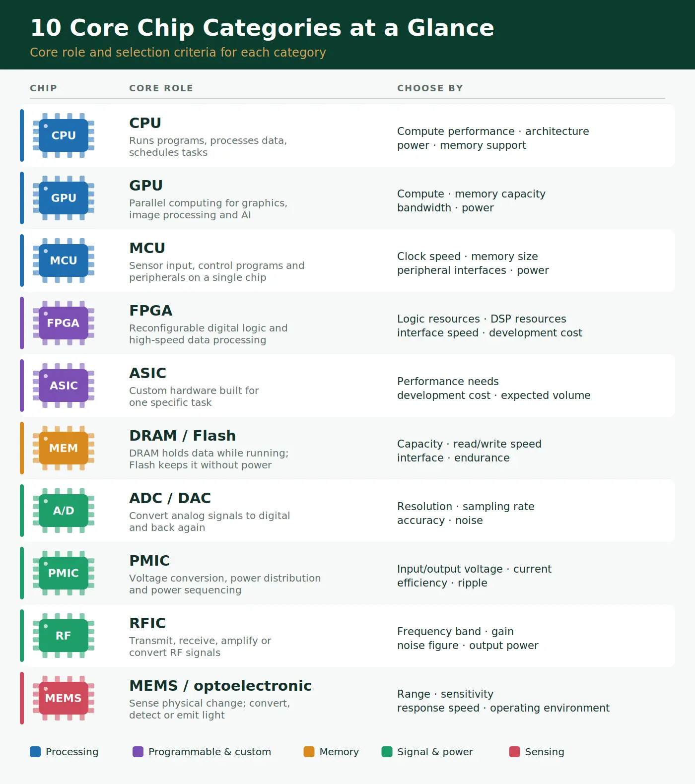
These categories overlap in practice. An SoC integrates a CPU, memory and other blocks on one die, many MCUs include ADCs, and some FPGAs include processor cores. Use the table to decide which function you need, then check the datasheet for how a specific part combines them.
The CPU is the general-purpose processor. It executes programs, processes data and handles task scheduling, and it is strongest at varied, sequential workloads with a mature software ecosystem. Select by compute performance, architecture, power and the memory it supports. High-performance CPUs usually come in dense BGA or LGA packages, which drives layer count, power delivery and thermal design; see our comparison of LGA vs BGA packages.
A GPU performs large numbers of similar calculations in parallel, which suits graphics rendering, image processing and AI computation. Compare compute, memory capacity, bandwidth and power. Its PCB demands are similar to a high-end CPU, with the memory interface and power delivery adding to the design effort. For the AI hardware landscape, see GPU vs TPU vs ASIC vs FPGA.
An MCU puts a processor core, memory, timers and peripherals such as ADCs on one chip. It collects sensor data, runs control programs and drives outputs, and it is the default choice for appliances, automotive electronics and industrial control. Select by clock speed, memory size, peripheral interfaces and power consumption. On the board, place decoupling close to every power pin and keep analog inputs away from fast digital lines; our ESP32 vs STM32 comparison shows how these layout rules differ between designs. For a broader comparison of processor families, see CPU, MCU, MPU, SoC, DSP, ECU, GPU and FPGA differences.
An FPGA implements custom digital logic by configuring its hardware, so the logic can be reworked after the board is built. Its strengths are parallel processing and reconfigurability, which suits high-speed acquisition, communications and prototype validation. Compare logic resources, DSP resources, interface speed and development cost. FPGAs typically need several supply rails, so check the datasheet for power-up sequencing requirements, and plan BGA fanout early. For the trade-offs against microcontrollers, see FPGA vs MCU.
An ASIC is designed for one task, so its computing or control function can be optimized for performance, power and die area. It makes sense when requirements are fixed, performance matters, and expected volume justifies the development cost; typical uses include AI acceleration and networking. When you use an ASIC-based part, follow the vendor's reference design and layout guidelines. Our guide to the AI ASIC covers what this means for PCB design.
DRAM holds data while the system runs and is fast, but it loses its contents when power is removed. Flash retains data without power, which makes it the choice for firmware and storage. Most computers, phones, SSDs and embedded systems use both. Select by capacity, read and write speed, interface and endurance. DDR memory needs matched routing and tight decoupling following the controller vendor's guidance, while an external flash chip mainly needs a short, clean connection to its controller. Our guide to decoupling capacitor placement covers the power side of memory design.
An ADC converts an analog signal into digital data, and a DAC converts digital data back into an analog signal. They link real-world signals to digital systems in sensor acquisition, audio equipment and industrial instruments. Compare resolution, sampling rate, accuracy and noise. Accuracy depends heavily on layout: keep the analog section separated from switching digital signals, and give the reference a clean, stable supply. The STM32U575 pinout guide shows how a microcontroller with built-in ADC and DAC separates analog supply and reference pins.
A power management IC handles voltage conversion, power distribution and power sequencing. Because it integrates several functions, it can simplify power design and save board space in phones, smart hardware and embedded boards. Check input and output voltage, current, conversion efficiency and ripple. Follow the datasheet for the recommended inductors and capacitors, keep switching loops small, and provide the thermal pad connection the package requires; our SMD packages guide explains why QFN thermal pads need thermal vias.
An RF IC processes wireless signals by transmitting, receiving, amplifying or converting them, and integrates key RF functions to reduce the size of a wireless system. It is used in Wi-Fi, Bluetooth and cellular communication. Compare operating frequency band, gain, noise figure and output power. RF traces generally need controlled impedance, commonly 50 ohms, and the RF section should be separated from digital switching noise. See what an RF PCB is for the layout principles, and our ESP32 antenna design guide for a practical module example.
MEMS devices sense or act on physical changes, such as acceleration or pressure, while optoelectronic chips convert, detect or emit light. Their small size and easy integration make them common in accelerometers, pressure sensors, cameras and optical communication. Select by measurement range, sensitivity, response speed and operating environment. On the board, follow the manufacturer's land pattern and handling notes, and consider placement relative to mechanical stress and heat sources, since both can affect sensor readings.
A real product combines several categories. A battery-powered wireless sensor, for example, might use a MEMS sensor, an ADC for analog inputs, an MCU to run the firmware, Flash for program storage, an RFIC for wireless communication, and a PMIC to power everything from a battery. Each connection between categories is a layout decision: where analog meets digital, where RF meets switching power, and where high-speed memory meets its controller.
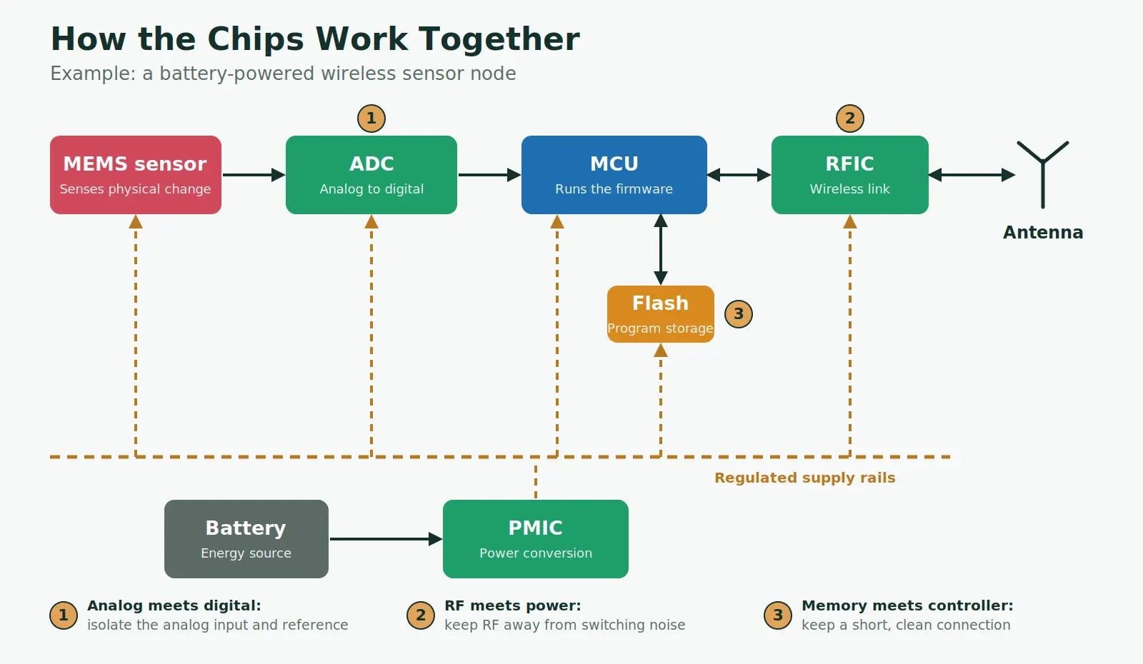
Block diagram of a battery-powered wireless sensor node showing MEMS sensor, ADC, MCU, Flash, RFIC, antenna, PMIC and battery
For a broader introduction to the other parts on a board, see our guides to electronic components and key PCB parameters and circuit board components.
If your design mixes several of these chip types, the NextPCB engineering team can review your layout and BOM before production. Our BOM service checks submitted part numbers against live marketplace stock and flags lead-time risk and possible alternates at the quoting stage.
Common practical categories are CPU, GPU, MCU, FPGA, ASIC, memory (DRAM and Flash), ADC and DAC converters, power management ICs, RF ICs, and MEMS or optoelectronic devices. They are grouped by function, and real parts often combine more than one.
An MCU integrates a processor core, memory, timers and input and output peripherals on one chip and is designed for control tasks. A CPU focuses on general-purpose computing and normally relies on external memory and peripherals.
Choose an FPGA when you need reconfigurable logic, are validating a design, or expect lower volume. Choose an ASIC when requirements are fixed, performance and power must be optimized, and expected volume justifies the development cost.
DRAM holds data while the system is running and is fast, but it loses its contents without power. Flash keeps data when power is off, so it stores firmware and files. Most systems use both.
An ADC converts an analog signal into digital data, for example when reading a sensor. A DAC converts digital data into an analog signal, for example when producing audio or a control voltage.
It depends on the type. High-speed digital chips such as CPUs, GPUs, FPGAs and DDR memory need careful power delivery and routing. Precision ADCs, DACs and RF ICs need noise isolation and, for RF, controlled impedance. PMICs need compact switching loops and thermal design.

Still, need help? Contact Us: support@nextpcb.com
Need a PCB or PCBA quote? Quote now