In the world of high-performance electronics—particularly in RF (Radio Frequency) and Microwave applications—"Rogers PCB" is a name that commands respect. For many engineers, it is not just a brand; it is synonymous with high frequency, high speed, and superior reliability.
This guide provides an in-depth look at Rogers PCBs, comparing them with standard materials and providing a detailed specification list of Rogers materials available at NextPCB.
What is a Rogers PCB?
A Rogers PCB refers to a printed circuit board manufactured using laminates produced by the Rogers Corporation. Unlike traditional FR-4 boards, which use epoxy resin and glass fiber, Rogers laminates are typically based on ceramics, hydrocarbons, or PTFE (Polytetrafluoroethylene) composites.
These materials are engineered to maintain extremely low signal loss and a highly stable Dielectric Constant (Dk) even at very high frequencies (up to 110 GHz).
Source: https://www.rogerscorp.com/advanced-electronics-solutions/ro4000-series-laminates/ro4000-lopro-laminates
Why Choose Rogers? Core Advantages
While Rogers materials come at a higher cost than standard FR-4, they offer specific performance characteristics that are non-negotiable for designs operating above 500MHz.
- Extremely Low Dielectric Loss: With a Dissipation Factor (Df) as low as 0.0009, Rogers materials minimize signal attenuation.
- Stable Dielectric Constant (Dk): Dk remains consistent across frequency and temperature changes, which is vital for impedance control.
- Superior Thermal Management: Materials like the RO4000 series offer high thermal conductivity to prevent overheating in power amplifiers.
- Low Moisture Absorption: Ideal for outdoor base stations and automotive radar sensors.
Rogers PCB vs. FR-4: Key Differences
| Feature |
Rogers Material (e.g., RO4350B) |
Standard FR-4 |
Performance Impact |
| Frequency |
Ideal for > 1GHz (RF/Microwave) |
Typically < 1GHz |
Rogers maintains signal clarity at high frequencies. |
| Dissipation Factor (Df) |
Very Low (~0.0037) |
Higher (~0.020) |
Rogers minimizes signal transmission loss. |
| Dielectric Constant (Dk) |
Stable & Precise |
Fluctuates |
Rogers allows for precise impedance control. |
NextPCB Expert Tip: To balance performance and budget, consider a Hybrid Buildup. Use Rogers material for critical signal layers and standard FR-4 for power/ground layers.
> Not sure whether to choose Rogers or FR4 for your design? Read our practical Rogers vs FR4 guide (Dk/Df, cost, and hybrid stackup decision matrix)
NextPCB High-Frequency PCB Materials
At NextPCB, we understand that selecting the right material is the first step to a successful RF design. NextPCB’s PCB manufacturing capabilities cover both PTFE and non-PTFE Rogers laminates for consumer to extremely high-frequency applications.
Below is a list of the most popular Rogers materials we support. For other low-loss options, you can also view our high-speed materials.
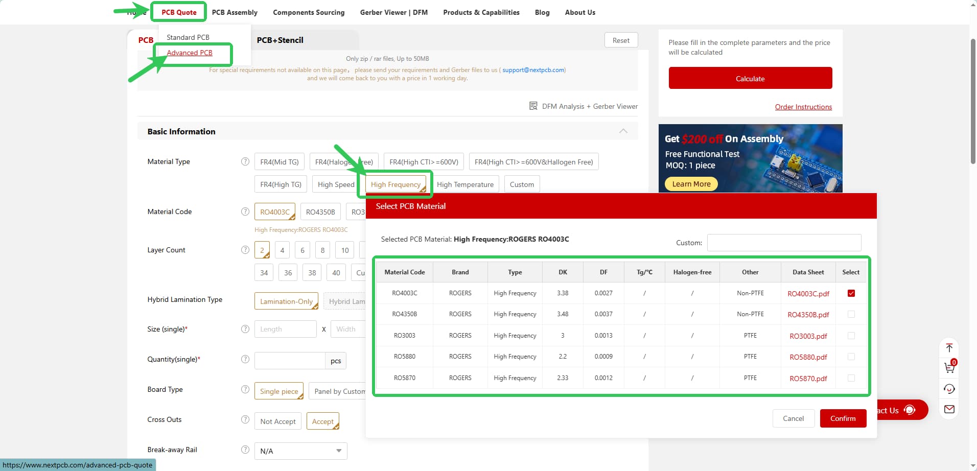
Popular Rogers Materials Specification Table
| Material Code |
Brand |
Max Freq |
Df (@10GHz) |
Dk (@10GHz) |
Tg/Td (°C) |
CTE (ppm/°C) X/Y/Z |
Type |
Datasheet |
| RO4003C |
ROGERS |
30 GHz |
0.0027 |
3.38 |
280 (TMA) |
11 / 14 / 46 |
Hydrocarbon / Ceramic / Woven Glass |
RO4003C.pdf |
| RO4350B |
ROGERS |
30 GHz |
0.0037 |
3.48 |
280 (TMA) |
14 / 16 / 50 |
Hydrocarbon / Ceramic / Woven Glass |
RO4350B.pdf |
| RO3003 |
ROGERS |
77 GHz |
0.0013 |
3.00 |
500 (TGA) |
17 / 16 / 25 |
PTFE + Ceramic Filling |
RO3003.pdf |
| RO5880 |
ROGERS |
110 GHz |
0.0009 |
2.20 |
500 (TGA) |
22 / 28 / 173 |
Reinforced PTFE |
RO5880.pdf |
| RO5870 |
ROGERS |
110 GHz |
0.0012 |
2.33 |
500 (TGA) |
31 / 48 / 237 |
Reinforced PTFE |
RO5870.pdf |
>> For more detailed information on Rogers materials, feel free to contact us at support@nextpcb.com
Note on Selection:
- RO4000 Series (RO4350B/RO4003C): Best balance of performance and cost. Easy to process (compatible with FR-4 processes).
- RO3000 Series: Excellent Dk stability, ideal for automotive radar (77 GHz).
- RT/duroid (RO5880): Ultra-low loss for millimeter-wave and aerospace applications.
NextPCB Rogers Manufacturing Capabilities
| Specification Item |
Technical Capabilities / Details |
| Layer Count |
2-6 layers; supports pure multilayer and hybrid stack-ups |
| Board Thickness |
0.203mm - 2.4mm (refers to base substrate thickness for 2-layer boards) |
| Material Types |
Rogers 4350B, Rogers 4003C |
| Min. Trace Width/Spacing |
3.5mil / 3.5mil |
| Min. Hole Size |
0.15mm |
| Solder Mask Colors |
Green, Blue, Red, Yellow, Black, Matte Black, White |
| Via Coverage |
Via plugging with ink, via plugging with resin + copper capping (POFV) |
| Surface Finish |
ENIG (1μ" - 3μ"), OSP, Immersion Tin, Immersion Silver |
| Special Processes |
Castellated holes (half-cut), Edge plating, Press-fit holes, Blue mask, Carbon ink |
| Testing Methods |
AOI + 4-wire low resistance flying probe full testing |
Detailed Characteristics and Commercial Parameters (4350B & 4003C)
| Property |
RO4003C
LoPro |
RO4350B
LoPro |
Direction |
Units |
Condition |
Test Method |
Dielectric Constant, εr
Process |
3.38 ± 0.05 |
3.48 ± 0.05 |
Z |
- |
10GHz/23°C |
IPC-TM-650 2.5.5.5
Stripline Resonator |
Dielectric Constant, εr
Design |
3.55 |
3.66 |
Z |
- |
8-40 GHz |
Differential Phase Length Method |
Dissipation Factor
tan δ |
0.0027
0.0021 |
0.0037
0.0031 |
Z |
- |
10GHz/23°C
2.5GHz/23°C |
IPC-TM-650
2.5.5.5 |
| Thermal Coefficient of εr |
+40 |
+50 |
Z |
ppm/°C |
-50 to 150°C |
IPC-TM-650 2.5.5.5 |
| Volume Resistivity |
1.7 x 10¹⁰ |
1.2 x 10¹⁰ |
|
MΩ•cm |
COND A |
IPC-TM-650 2.5.17.1 |
| Surface Resistivity |
4.2 x 10⁹ |
5.7 x 10⁹ |
|
MΩ |
COND A |
IPC-TM-650 2.5.17.1 |
| Electrical Strength |
31.2
(780) |
31.2
(780) |
Z |
KV/mm
(V/mil) |
0.51mm
(0.020") |
IPC-TM-650
2.5.6.2 |
| Tensile Modulus |
26,889 (3900) |
11,473 (1664) |
Y |
MPa (kpsi) |
RT |
ASTM D638 |
| Tensile Strength |
141 (20.4) |
175 (25.4) |
Y |
MPa (kpsi) |
RT |
ASTM D638 |
| Flexural Strength |
276 (40) |
255 (37) |
|
MPa (kpsi) |
|
IPC-TM-650 2.4.4 |
| Dimensional Stability |
<0.3 |
<0.5 |
X,Y |
mm/m
(mils/inch) |
After Etch
+E2/150°C |
IPC-TM-650 2.4.39A |
| Coefficient of Thermal Expansion |
11
14
46 |
14
16
35 |
X
Y
Z |
ppm/°C |
-55 to 288°C |
IPC-TM-650 2.1.41 |
| Tg |
>280 |
>280 |
|
°C TMA |
A |
IPC-TM-650 2.4.24.3 |
| Td |
425 |
390 |
|
°C TGA |
|
ASTM D3850 |
| Thermal Conductivity |
0.64 |
0.62 |
|
W/m/°K |
80°C |
ASTM C518 |
| Moisture Absorption |
0.04 |
0.05 |
|
% |
0.060" thickness
48h immersion
50°C |
ASTM D570 |
| Density |
1.8 |
1.9 |
|
gm/cm3 |
23°C |
ASTM D792 |
| Copper Peel Strength |
1.05 (6.0) |
0.88 (5.0) |
|
N/mm (pli) |
1 oz. TC after solder float |
IPC-TM-650 2.4.8 |
| Flammability UL94 |
N/A |
V-0 |
|
|
|
UL 94 |
| Lead-Free Process Compatible |
Yes |
Yes |
|
|
|
|
For more information, please see the Rogers official website.
Pure Rogers PCB Stack-up Structure
1. Definition
This refers to a PCB where all conductive and dielectric layers are laminated using Rogers high-frequency materials. It can be laminated using the same model of Rogers boards, or a combination of different Rogers board models. Currently, NextPCB only supports pure stack-up structures laminated with the same model of Rogers boards.
2. Structure Diagram
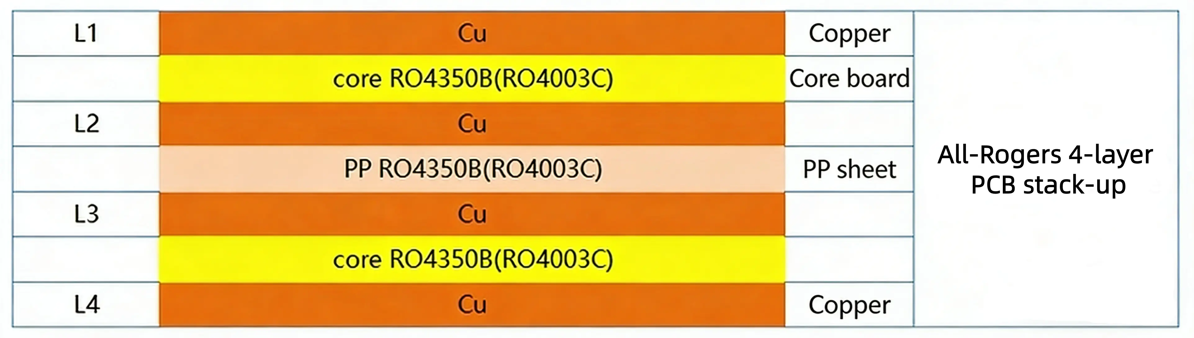
Figure 1: 4-Layer Pure Rogers Stack-up Structure
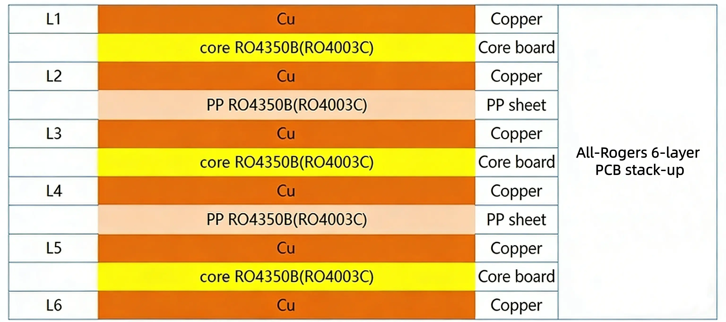
Figure 2: 6-Layer Pure Rogers Stack-up Structure
3. Process Features & Advantages
- Ultimate Performance: Fully utilizes the low-loss characteristics of Rogers materials, providing optimal high-frequency performance.
- Precise Impedance Control: Due to the single dielectric material and consistent dielectric constant, the impedance calculation model is straightforward, resulting in high control accuracy.
- High Reliability: The well-matched Coefficient of Thermal Expansion (CTE) of the materials ensures excellent lamination bonding reliability.
4. Applicable Scenarios
- Microwave and millimeter-wave circuits (e.g., radar front-ends, satellite communication modules).
- High-speed digital circuits with extremely strict signal integrity requirements (e.g., 100G+ optical modules).
- 77GHz radar sensors in automotive electronics.
Rogers and FR-4 Hybrid Stack-up Structure
1. Definition
This refers to a structure where the core boards are laminated using a combination of Rogers high-frequency boards and FR-4 boards. It can involve the lamination of the same model of Rogers high-frequency board with FR-4, or different models of Rogers high-frequency boards with FR-4. Currently, NextPCB only supports the lamination of a single Rogers core board with FR-4.
2. Structure Diagram
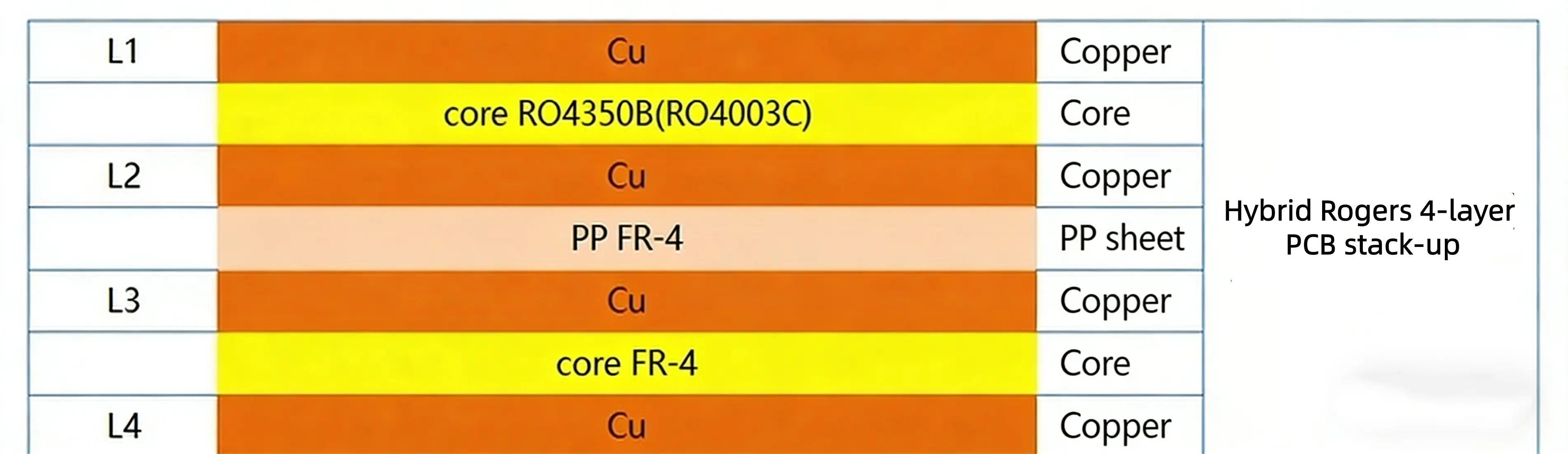
Figure 3: 4-Layer Hybrid Stack-up Structure
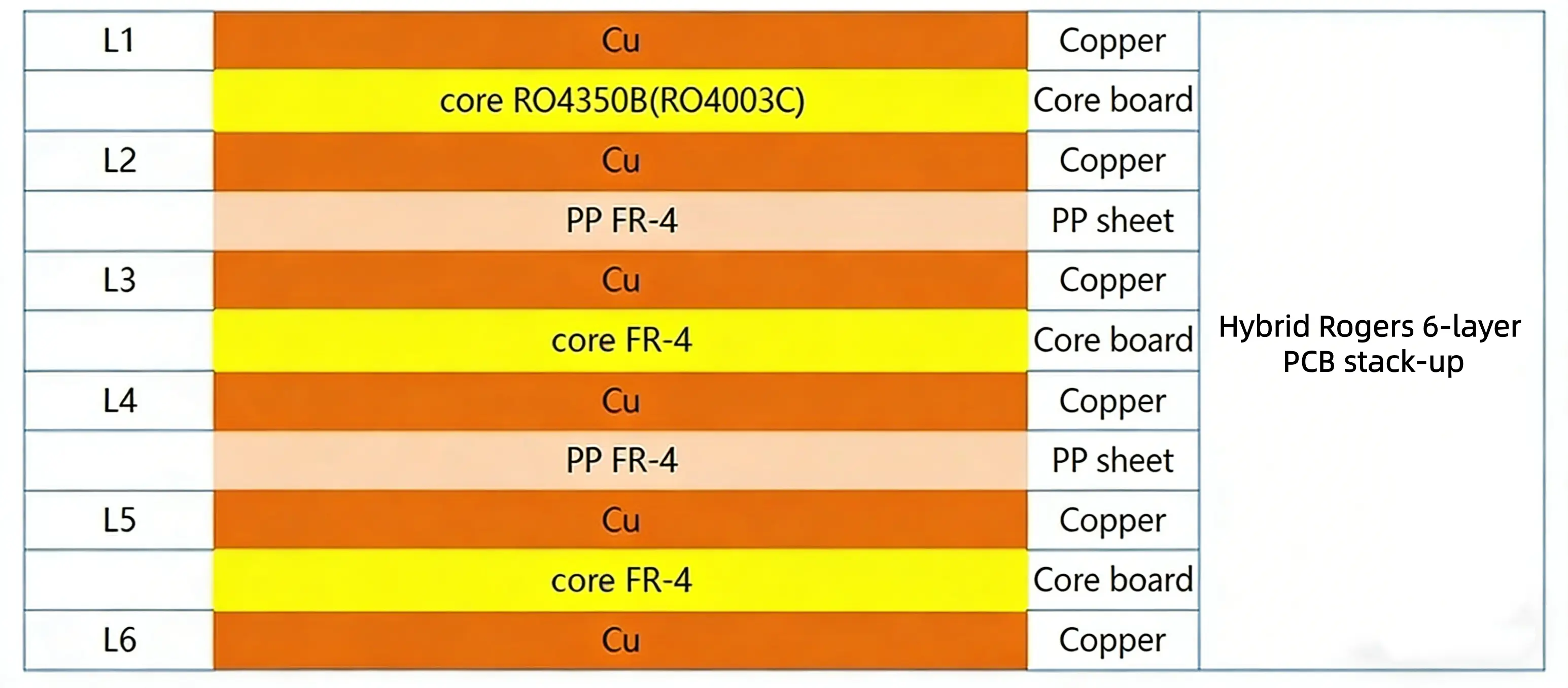
Figure 4: 6-Layer Hybrid Stack-up Structure
Conclusion
Choosing a Rogers PCB is a commitment to signal integrity. Whether you are designing a 77GHz automotive radar using RO3003 or a cost-effective microwave link using RO4350B, NextPCB has the stock and the manufacturing expertise to bring your design to life.
Ready to start? Visit our Online Quote System to upload your Gerber files, or contact our engineering team for advice on material selection and stack-up design.
Frequently Asked Questions (FAQs) About Rogers PCB Fabrication
Q1: Why are Rogers PCBs more expensive than standard FR4?
A: Rogers materials are engineered for high-frequency, RF, and microwave applications. They lack the glass fiber network found in standard FR4, using specialized ceramic bases or PTFE materials instead. This provides significantly lower signal loss (Df) and a stable dielectric constant (Dk), but the raw materials and the specialized machining processes required (such as specific drilling speeds and plasma desmearing) increase the overall fabrication cost.
Q2: Can I reduce costs by combining Rogers material with FR4?
A: Yes! This is called a "Hybrid Stackup." For multi-layer boards, you can use Rogers material only for the outer layers where critical high-frequency routing occurs, and use standard FR4 for the inner power/ground planes and low-speed signal layers. NextPCB specializes in hybrid stackup fabrication to help you achieve RF performance without breaking your budget.
Q3: What is the difference between RO4350B and RO4003C?
A: Both are highly popular hydrocarbon ceramic laminates. RO4003C has a lower Dk (3.38) and is generally more cost-effective, but it does not have a UL 94V-0 flammability rating. RO4350B (Dk 3.48) is slightly more expensive but includes brominated flame retardants to achieve the UL 94V-0 rating, making it mandatory for many consumer and commercial applications.
Q4: Do Rogers PCBs require special surface finishes?
A: While you can use various finishes, ENIG (Electroless Nickel Immersion Gold) or Immersion Silver are highly recommended for Rogers PCBs. Hot Air Solder Leveling (HASL) can create uneven surfaces which negatively impact high-frequency transmission lines and impedance control. Immersion finishes ensure a flat surface for tight-pitch RF components.
Q5: What are the typical lead times for Rogers PCB manufacturing?
A: Standard FR4 prototypes can be done in 24-48 hours, but Rogers PCB fabrication typically takes longer (around 5 to 10 days) due to the specialized lamination cycles and potential raw material sourcing. However, at NextPCB, we maintain a steady stock of common Rogers laminates (like RO4350B) to ensure rapid prototyping and accelerated lead times for your RF projects.

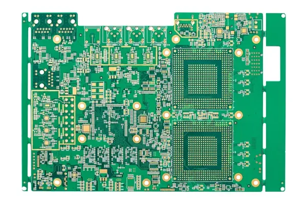
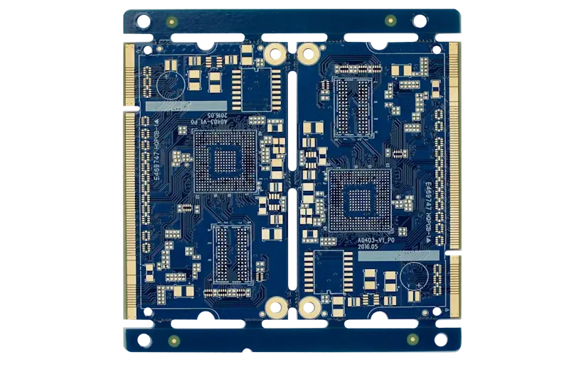
 NextPCB Capabilities
 PCB Assembly
 Layer Buildup
 SMD-Stencils
 PCB Design-Aid & Layout
 Mechanics
 Surface
 Quality
 Drills & Throughplating
 Factory & Certificate