
 Surface


Julia Wu - Senior Sales Engineer at NextPCB.com

 NextPCB Capabilities
Printed Circuit Boards
NextPCB Capabilities
Printed Circuit Boards
 PCB Assembly
 Layer Buildup
 SMD-Stencils
 PCB Design-Aid & Layout
 Mechanics
 Quality
 Drills & Throughplating
 Factory & Certificate
 PCB Assembly Factory Show
Certificate
PCB Assembly Factory Show
Certificate
Support Team
Feedback:
support@nextpcb.com


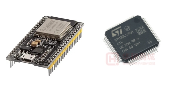
This question comes up in almost every embedded project that sits somewhere between a simple sensor node and a full industrial controller. The ESP32 and the STM32 are both 32-bit microcontrollers with large ecosystems, active communities, and years of proven production use. They are also built on fundamentally different assumptions about what embedded hardware should prioritize, and picking the wrong one does not just make development harder — it can require a hardware respin once the project runs into the wall the wrong chip was always going to hit.
This article compares them across the dimensions that actually drive real design decisions: architecture, real-time performance, wireless connectivity, peripheral depth, power consumption, development tooling, PCB design implications, and cost. At the end, a decision framework maps specific project requirements to the right platform — including the cases where the right answer is both, running together.
The ESP32, developed by Espressif Systems and first released in 2016, was built around a single premise: make wireless connectivity so cheap and integrated that developers stop thinking of it as a separate problem. Before ESP32, adding Wi-Fi to a microcontroller project meant a separate transceiver IC, antenna matching network, regulatory certification, and firmware complexity. ESP32 folded all of that into a single $2–3 SoC. That decision shaped everything about the chip — its architecture, its peripheral set, its power profile, and the community that formed around it.
The STM32 family, developed by STMicroelectronics and spanning decades of product generations, was built around a different premise: give engineers a scalable, deterministic, ARM-based platform that works predictably across the widest possible range of embedded applications. The STM32 family runs from the STM32L0 (Cortex-M0+, as little as 8 KB flash, designed to run for years on a coin cell) to the STM32H7 (Cortex-M7 at 550 MHz, dual-core on some variants, 2 MB flash, 1 MB RAM). That range of options within a single ecosystem, all sharing the same toolchain and peripheral library structure, is itself a design philosophy.
Neither platform is trying to be the other. The comparison becomes useful only when you understand what each one was optimized for, and which of those optimizations matches what your project actually needs.
The ESP32 uses Espressif's Tensilica Xtensa LX6 dual-core architecture, with each core running at up to 240 MHz. Combined, the two cores deliver approximately 600 DMIPS. The newer ESP32-S3 uses the faster LX7 core, pushing single-core performance higher, while the C3 and C6 variants shift to RISC-V for lower cost. The dual-core design is practically useful: the Wi-Fi and Bluetooth stacks run on one core, leaving the second core free for application code without the stack overhead affecting timing.
The STM32 family spans the ARM Cortex-M hierarchy. At the low end, the STM32F103 (Cortex-M3, 72 MHz) delivers around 90 DMIPS. The STM32F4 series (Cortex-M4 with FPU, 168–180 MHz) reaches roughly 210 DMIPS and adds hardware floating-point. At the high end, the STM32H7 (Cortex-M7 with double-precision FPU, 480–550 MHz) exceeds 1000 DMIPS and includes an L1 cache and tightly coupled memory for deterministic high-speed access. Some STM32H7 variants are dual-core (Cortex-M7 + Cortex-M4).
Raw comparison between the platforms is complicated by the fact that ESP32 competes with mid-range STM32 parts on clock speed but not on architecture maturity. The Cortex-M architecture benefits from decades of compiler optimization, RTOS tuning, and mathematical library development. The Xtensa LX6 is capable but narrower in toolchain breadth. In practice, for the majority of IoT tasks — sensor reading, protocol handling, JSON parsing, MQTT publishing — the ESP32's processing headroom is more than adequate. For DSP, motor control algorithms, or tight computational loops with floating-point math, the STM32F4 or H7 with hardware FPU is measurably faster and more efficient.
| Parameter | ESP32 (standard) | ESP32-S3 | STM32F4 | STM32H7 |
|---|---|---|---|---|
| Core | Xtensa LX6 dual-core | Xtensa LX7 dual-core | ARM Cortex-M4 + FPU | ARM Cortex-M7 + FPU |
| Max clock | 240 MHz | 240 MHz | 180 MHz | 480–550 MHz |
| DMIPS (approx.) | ~600 (both cores) | ~800 (both cores) | ~210 | ~1000+ |
| Hardware FPU | No (LX6); limited (S3) | Single-precision | Single-precision | Double-precision |
| Cache / TCM | No L1 cache | No L1 cache | No L1 (some models ART) | L1 cache + TCM |
| SRAM | 520 KB | 512 KB + up to 8 MB PSRAM | 192 KB–364 KB | Up to 1 MB |
| Flash (internal) | External (via SPI, 4–16 MB) | External (via SPI) | 512 KB–2 MB | Up to 2 MB |
One structural difference worth noting: the ESP32 has no internal flash. Program storage sits in an external SPI flash chip, which the module accesses over a dedicated bus. This is transparent in normal operation but becomes relevant in code execution speed (external flash reads are slower than internal) and in power management (the flash chip draws current independently). STM32 devices store code in internal flash, which the processor accesses via high-speed buses with hardware prefetch and cache on the higher-end parts.
This is where the platforms diverge most sharply, and where the most common mistakes in platform selection happen.
The STM32 is an ARM Cortex-M device, and the Cortex-M architecture was designed from the ground up for deterministic interrupt handling. Interrupt latency on a Cortex-M4 or M7 is fixed and measurable: typically 12 clock cycles from interrupt assertion to the first instruction of the ISR, guaranteed by the architecture. Advanced timers on the STM32 support hardware PWM generation, encoder input, and commutation triggering for motor control without CPU involvement. DMA controllers on STM32 are genuinely advanced, with full memory-to-peripheral and peripheral-to-memory transfers that run independently of the CPU and can chain to each other. The combination of deterministic interrupts, hardware timers, and autonomous DMA is what makes STM32 the standard choice in motor drives, servo controllers, and industrial automation.
The ESP32 runs FreeRTOS and handles real-time tasks through RTOS tasks and interrupt service routines. For most IoT applications — reading a sensor every 100 ms, responding to a button press, publishing to an MQTT broker — this is completely adequate. The dual-core architecture helps because the networking stack, which can hold the CPU for unpredictable durations during Wi-Fi activity, runs on a separate core from the application. However, the ESP32 does not provide hard real-time guarantees in the same architectural sense that the STM32 does. Interrupt latency can vary due to cache misses (external flash), wireless interrupt activity on the networking core, and the overhead of the FreeRTOS scheduler. For applications that require microsecond-level timing precision or hard guarantees on worst-case latency, STM32 is the correct choice and ESP32 is not.
| Real-Time Characteristic | ESP32 | STM32 |
|---|---|---|
| Interrupt latency | Variable; affected by Wi-Fi activity and external flash | Fixed; typically 12 cycles on Cortex-M4/M7 |
| Hard real-time guarantee | No | Yes |
| Hardware PWM | Yes (LEDC, MCPWM modules) | Yes (advanced timers with dead-time, complementary outputs) |
| Motor control support | Adequate for hobby / medium complexity | Industrial-grade; hardware FOC support on some families |
| DMA | Yes; basic multi-channel | Yes; advanced with chaining, DMAMUX on newer families |
| RTOS | FreeRTOS (built into SDK) | FreeRTOS, Zephyr, ThreadX, bare-metal |
The ESP32's defining feature is integrated wireless. Wi-Fi 802.11 b/g/n at 2.4 GHz and dual-mode Bluetooth (Classic + BLE 5.0) are built into the silicon. No external transceiver, no antenna matching network to design, no separate firmware stack to port. The ESP32-C6 adds Wi-Fi 6 (802.11ax) and 802.15.4 (Zigbee/Thread), making it capable of running Matter natively over both Wi-Fi and Thread. Pre-certified modules (WROOM, MINI series) mean that designs can inherit FCC and CE certification without a full radio certification process, which alone can save $5,000–$15,000 per product.
The STM32 family does not include Wi-Fi or Bluetooth in most parts. Adding wireless connectivity to an STM32 design requires an external transceiver — typically an ESP32 acting as a Wi-Fi co-processor, a Murata or u-blox module, or a dedicated SPI/UART Wi-Fi chip. The exceptions are Bluetooth-specific: the STM32WB series integrates a Cortex-M0+ alongside the main M4 core dedicated to BLE and Zigbee stacks, and the STM32WL integrates a sub-GHz radio for LoRaWAN. If you specifically need Wi-Fi on STM32, you are adding hardware, BOM cost, PCB complexity, and a separate certification burden.
Where STM32 dominates is wired industrial connectivity. CAN bus (classic CAN and CAN-FD on newer families), USB full-speed and high-speed, Ethernet MAC with MII/RMII interfaces, I²C, SPI, UART, SAI, SDMMC, and FDCAN are available across the STM32 family at a level of peripheral maturity that reflects decades of industrial deployment. The ESP32 has wired interfaces (I²C, SPI, UART, I²S, Ethernet MAC on some variants) but no native CAN bus, no native USB OTG on the original ESP32 (S3 adds it), and no on-chip Ethernet PHY.
| Connectivity | ESP32 | STM32 |
|---|---|---|
| Wi-Fi | ✓ Built-in (Wi-Fi 4; C6 has Wi-Fi 6) | ✗ External module required |
| Bluetooth / BLE | ✓ Built-in BLE 5.0 (Classic on original ESP32) | ✓ STM32WB only; external otherwise |
| Zigbee / Thread | ✓ ESP32-C6, ESP32-H2 | ✓ STM32WB (BLE + Zigbee) |
| CAN / CAN-FD | ✗ Not available | ✓ Available on F/G/H/U families |
| USB OTG | ✓ ESP32-S3 only; Serial/JTAG on C3 | ✓ Full-speed and high-speed on F/H families |
| Ethernet MAC | ✓ Some variants (external PHY required) | ✓ Multiple families (external PHY required) |
| RF pre-certification | ✓ Module variants (WROOM, MINI) | ✗ Full certification required for wireless |
For products that need Wi-Fi connectivity, the ESP32 collapses what would otherwise be a multi-chip, multi-certification engineering problem into a single component decision. For products that need CAN bus, high-speed USB, or industrial-grade Ethernet, STM32 is the natural choice — and those products often do not need Wi-Fi at all.
Ready to take your microcontroller choice to hardware?
Whether you are designing an ESP32 IoT node or an STM32 industrial controller, NextPCB supports controlled-impedance fabrication, 2–20 layer stackups, and DFM review before production. Get an instant PCB prototype quote →
The ESP32 has 18 ADC channels across two units (ADC1 and ADC2), both 12-bit SAR converters. There is one constraint that catches designs off guard repeatedly: ADC2 channels cannot be used while Wi-Fi is active. The Wi-Fi radio and ADC2 share internal circuitry. For any design that combines Wi-Fi with analog measurement, only ADC1 channels (GPIO32–GPIO39) are reliably usable. The ESP32 also has two 8-bit DAC channels and ten capacitive touch sensing GPIOs. Timer peripherals include general-purpose timers and the MCPWM module for motor control, but they lack the hardware dead-time insertion, fault protection, and complementary outputs found in STM32's advanced timers.
STM32 ADC peripherals are a different class of component. The STM32F4 provides three 12-bit ADCs with up to 24 channels and simultaneous sampling. The STM32H7 adds 16-bit ADC resolution on some channels and supports hardware oversampling for noise reduction without CPU intervention. Timer peripherals on STM32 are the standard reference for motor control in embedded systems: advanced timers with hardware dead-time generation, complementary PWM outputs, encoder interface mode, and commutation event triggers allow field-oriented control (FOC) of brushless motors with minimal CPU involvement. For applications requiring precision analog — current sensing, power metering, scientific instruments, audio — STM32 provides ADC specifications that the ESP32 does not reach.
| Peripheral | ESP32 | STM32 (mid-high range) |
|---|---|---|
| ADC channels | 18 × 12-bit (ADC2 unavailable with Wi-Fi) | Up to 24 × 12-bit (H7: up to 16-bit) |
| ADC simultaneous sampling | No | Yes (dual/triple ADC mode) |
| DAC | 2 × 8-bit | 2 × 12-bit (on supported families) |
| Advanced motor control timers | MCPWM (basic) | TIM1/TIM8 with dead-time, fault, complementary outputs |
| Touch sensing | 10 capacitive GPIO pins | Available via TSC peripheral (select families) |
| CAN bus | Not available | bxCAN, FDCAN on F/G/H/U families |
| Crypto / security | AES, SHA, RSA, ECC, Secure Boot, Flash encryption | AES, SHA, PKA, TrustZone on STM32U5/H5/L5 |
Both platforms support deep sleep modes with single-digit microamp consumption. In deep sleep, the ESP32 can draw as little as 5 μA, and the STM32L series reaches 300 nA in shutdown mode with RTC running. At this level, the difference matters for applications that sleep for months between wake events (agricultural sensors, metering), but for most battery products it is not the deciding factor.
The meaningful difference appears in active mode. An ESP32 with Wi-Fi active draws 80–260 mA depending on transmission activity, with peak spikes up to 500 mA during association and data bursts. Without Wi-Fi, a typical ESP32 draws 40–80 mA at idle. An STM32F4 at 168 MHz draws approximately 100–150 mA. An STM32L4 in run mode at 80 MHz draws roughly 10–30 mA. An STM32L0 at low clock speeds can run the main application at under 5 mA.
For battery-powered products that need wireless connectivity, the ESP32 strategy is to spend most time in deep sleep, wake to connect, transmit, and return to sleep as fast as possible. The penalty for this approach is that Wi-Fi association takes 100–500 ms after each wake, during which current is high. For products that transmit frequently (every few seconds), the average current is high enough that this design pattern may not achieve the target battery life. For products that transmit infrequently (every 15 minutes or more), deep sleep with wake-to-transmit works well on a reasonably sized Li-Po cell.
| Power Mode | ESP32 | STM32L4 | STM32H7 |
|---|---|---|---|
| Deep sleep / shutdown | ~5 μA | ~8 nA (shutdown) | ~2.2 μA |
| Active (no radio) | 40–80 mA | 10–30 mA | 100–300 mA |
| Wi-Fi active TX | 160–500 mA peak | N/A (no built-in Wi-Fi) | N/A (no built-in Wi-Fi) |
| Best for battery | Infrequent transmission cycles | Long-duration low-power sensing | Mains-powered high-performance |
The ESP32 development ecosystem is built around two primary paths. The first is Arduino IDE with the ESP32 Arduino core, which gives access to the Arduino library ecosystem and the lowest barrier to entry for developers coming from Arduino backgrounds. The second is ESP-IDF (Espressif IoT Development Framework), Espressif's official SDK built on FreeRTOS, which provides full access to all chip features and is used for production firmware. PlatformIO supports both approaches. MicroPython is also well-supported on ESP32 and is useful for rapid prototyping. The community around ESP32 on GitHub, Reddit, and forums like esp32.com is large and active.
The STM32 ecosystem is built around ST's own toolchain. STM32CubeIDE is ST's Eclipse-based integrated development environment that handles project configuration, peripheral initialization, and debugging. STM32CubeMX is a graphical pin and clock configurator that generates initialization code, reducing the manual effort of peripheral setup significantly. HAL (Hardware Abstraction Layer) and LL (Low-Layer) libraries are provided by ST for every peripheral on every chip. Beyond ST's official tools, STM32 has broad support from IAR Embedded Workbench, Keil MDK, and PlatformIO. Zephyr RTOS, FreeRTOS, and ThreadX all have strong STM32 support. The professional embedded developer survey data consistently shows STM32 as the most widely used MCU family among employed embedded engineers.
One practical difference: getting an ESP32 project running takes less time for most developers. Arduino IDE + ESP32 core, select the board, hit upload. STM32CubeIDE + CubeMX configuration, clock tree setup, peripheral initialization, build system configuration — the initial setup is more involved and assumes more familiarity with embedded development concepts. This is not a flaw in STM32; it reflects that the platform is aimed at developers who need precise control over every peripheral and timing parameter. But for teams that value time-to-first-blink over long-term configurability, ESP32 wins on setup speed.
The PCB design implications differ significantly between the two platforms and affect layout complexity, layer count decisions, and DFM requirements.
For ESP32-based designs, the most common approach is to use a pre-certified module (WROOM-32E, C3-MINI-1, S3-WROOM-1, etc.) mounted on a carrier PCB. This simplifies the RF design dramatically: the antenna, matching network, crystal, and flash are all inside the shielded module. The primary layout constraint is the antenna keep-out zone — a 15 mm clearance region around the antenna where no copper is permitted on any layer. Violating this region is the most common cause of poor Wi-Fi performance on first ESP32 custom PCBs. The module itself can sit on a 2-layer board for most applications, though 4-layer is recommended for designs with mixed analog and digital signals or significant switching noise. For more on ESP32 RF layout rules, see the ESP32 Antenna Design Guide.
STM32 devices are available in a wide range of packages, from LQFP32 (easy to hand-solder) to BGA-packages used in higher-density or higher-pin-count applications. The STM32's internal flash eliminates the SPI flash chip that ESP32 designs carry, reducing component count. Without an RF front end, there is no antenna keep-out requirement and no high-frequency RF trace to route. However, STM32 high-speed designs (H7 at 480 MHz, or any design with USB high-speed) have their own layout requirements: bypassing networks close to every power pin, controlled-impedance USB differential pairs, and careful separation of analog and digital ground domains near ADC inputs. LQFP packages with a thermal pad (present on some STM32 packages) require specific PCB via patterning for thermal performance — see NextPCB's STM32 thermal pad grounding guide for the details.
For an ESP32 4-layer IoT board designed in KiCad, the KiCad 9 ESP32 IoT PCB walkthrough on the NextPCB blog covers stackup selection, impedance specification, and the DFM checks that catch antenna keep-out and trace width issues before fabrication. For STM32 pinout and package selection across the LQFP64 to UFBGA169 range, the STM32 pinout and package layout guide covers footprint pitfalls and HDI routing considerations for BGA variants.
| PCB Design Factor | ESP32 (module) | STM32 (LQFP/QFP) |
|---|---|---|
| Antenna keep-out zone | Required; 15 mm on all layers | Not applicable |
| RF trace / matching network | Inside module (not your problem) | Not applicable |
| External flash chip | Inside module | Not needed (internal flash) |
| Minimum recommended layers | 2 (module designs); 4 (bare chip) | 2 for simple designs; 4+ for high-speed |
| Controlled impedance required | For U.FL / bare chip RF traces | For USB HS, Ethernet differential pairs |
| Thermal pad (PCB via required) | Module pads; standard via pattern | Some packages (LQFP, UFBGA); specific pattern |
| RF certification path | Module modular approval (simplified) | Full certification for wireless; N/A for wired-only |
ESP32 module costs have settled in the $2–4 range for standard WROOM variants at 10K+ quantities, with bare chips at $1.50–$2.50 depending on variant and volume. The integration of Wi-Fi, Bluetooth, flash, crystal, and antenna into the module means the BOM savings from going to bare chip rarely justify the engineering cost at volumes below 50,000 units. At 10–50K volume, the module is almost always the right economic choice even if the bare chip is $0.50 cheaper per unit, because the bare chip route adds RF engineering, certification cost, and VNA tuning time that exceed the BOM savings by a wide margin.
STM32 pricing varies enormously across the family. The STM32F103C8 (the "Blue Pill" chip) can be found at under $1 in volume. Mid-range F4 parts run $3–$8. The STM32H7 series at the high end runs $10–$25 per unit in volume. The correct comparison is not ESP32 module vs. STM32 chip, but ESP32 module vs. STM32 chip plus any required wireless module, at the relevant volume. When Wi-Fi is needed on STM32, the external module adds $3–$8 to the BOM, in addition to the STM32 itself, plus PCB area, additional regulatory certification, and firmware integration time.
Supply chain resilience is worth considering. ESP32 is manufactured exclusively by Espressif. During the 2020–2022 semiconductor shortage, ESP32 availability was constrained, and lead times stretched to 20+ weeks. STM32 is manufactured by ST with broader foundry relationships, but the F103 in particular had severe shortage issues during the same period. Neither platform is immune to supply risk. For high-volume or mission-critical production, qualified second-source components or buffer stock planning are worth building into the program.
| Category | ESP32 | STM32 |
|---|---|---|
| Architecture | Xtensa LX6/LX7 dual-core or RISC-V | ARM Cortex-M0 to M7 (broad family) |
| Max clock | 240 MHz | Up to 550 MHz (H7) |
| Wi-Fi | Built-in | External module required (except STM32WB/WL) |
| Bluetooth / BLE | Built-in | STM32WB only; external otherwise |
| CAN bus | None | Available (bxCAN, FDCAN) |
| USB OTG | S3 only | Multiple families |
| ADC resolution | 12-bit (ADC2 limited with Wi-Fi) | 12–16-bit; simultaneous sampling |
| DAC resolution | 8-bit | 12-bit |
| Hard real-time | No | Yes |
| Motor control | Basic (MCPWM) | Advanced (hardware FOC-capable timers) |
| Deep sleep current | ~5 μA | ~300 nA (L series) |
| Active current (no radio) | 40–80 mA | 5–150 mA (family-dependent) |
| Primary IDE | Arduino IDE / ESP-IDF / PlatformIO | STM32CubeIDE / Keil / IAR / PlatformIO |
| Learning curve | Lower for IoT / Arduino community | Steeper; more configurable |
| RF pre-certification | Module variants available | Not applicable for wired-only; full cert needed for wireless |
| Typical module cost (10K) | $2–4 (module, all-inclusive) | $1–25 (chip only, family-dependent) |
| Dominant use cases | IoT, smart home, BLE devices, connected prototypes | Industrial control, motor drives, automotive, medical, audio |
The choice is rarely about which chip is better in the abstract. It is about which chip's strengths align with what the project actually needs to do.
Choose ESP32 when:
Choose STM32 when:
The borderline cases: Smart home devices with both local control (fast motor, relay, ADC) and Wi-Fi reporting often end up on either platform with trade-offs either way. Industrial sensors that need occasional Wi-Fi OTA updates but mostly run tight measurement loops are genuinely ambiguous. Battery-powered BLE devices with complex analog front ends — wearables, medical monitors — are a serious design decision where STM32WB vs. ESP32 comes down to ADC spec, BLE stack maturity, and power budget in ways that warrant a genuine technical comparison at the architecture stage. Both the ESP32 pinout reference and the STM32 pinout and package guide are useful starting points when evaluating specific pin availability for borderline designs.
A design pattern that appears in serious production products more often than the comparison framing suggests: use both. The STM32 handles everything that requires deterministic real-time control — the motor loop, the safety interlock, the precise ADC sampling sequence. The ESP32 handles everything that requires networking — Wi-Fi connectivity, MQTT or HTTPS client, OTA firmware updates, user-facing BLE configuration. They communicate over UART or SPI.
This pattern costs more in BOM and PCB area than either chip alone, but it sidesteps every compromise. The STM32 gets its deterministic timing without Wi-Fi interrupt interference. The ESP32 gets its networking job without needing to emulate timer precision it was not designed for. Teams that have run into the limitations of both platforms individually often end up here on the second or third product generation. If the application requirements point at this combination, it is worth designing for it from the start rather than discovering the limitations of a single-chip approach during integration testing.
From schematic to assembled board — NextPCB handles both.
ESP32 IoT modules, STM32 industrial controllers, or mixed-architecture designs: NextPCB offers PCB fabrication, SMT assembly, BOM sourcing, and DFM review in one workflow. Get a free PCBA quote →
For most hobby and maker motor control projects, yes — the ESP32 MCPWM module handles basic DC motor speed control, simple servo positioning, and low-frequency brushless motor commutation without difficulty. For production motor drives, the answer is generally no. Industrial motor control relies on the STM32's advanced timers for hardware-generated complementary PWM with dead-time insertion, hardware fault protection that cuts PWM in microseconds, and encoder interface mode for position feedback — all running without CPU intervention. The ESP32 can implement these functions in software, but interrupt latency variation means timing precision degrades at higher switching frequencies, and the Wi-Fi stack sharing a core with the control loop creates unpredictable jitter. The STM32 motor control library (X-CUBE-MCSDK) is specifically built around the advanced timer architecture and has years of industrial validation behind it. If microsecond timing precision and hardware fault protection are required, STM32 is the correct platform.
It depends on what the Wi-Fi is for. If Wi-Fi is a core product feature — the device is always connected, the user interacts through a mobile app, OTA updates are frequent — then a dedicated ESP32 as a network co-processor is a reasonable design choice. The UART or SPI communication overhead between the two chips is manageable, and the architectural cleanliness of separating the real-time control domain from the network domain has genuine engineering value. If Wi-Fi is a peripheral feature — occasional OTA updates, infrequent status reporting — then an external Wi-Fi module with a simpler AT-command interface (UART-controlled) may be a cheaper and lower-complexity option than a full ESP32. The full ESP32 brings FreeRTOS, a full TCP/IP stack, and significant firmware complexity alongside its Wi-Fi capability. Matching that to the actual Wi-Fi requirement is worth doing before committing to the design.
This is genuinely contested territory. ESP32 in deep sleep at 5 μA for 15 minutes, wake, connect to Wi-Fi (100–500 ms at 200 mA), transmit a packet, return to sleep — average current across the cycle is dominated by the wake event but can be managed to a few hundred microamps average on a 15-minute cycle. On a 2000 mAh Li-Po cell, that translates to many months of operation if the wake event is short and efficient. An STM32L4 in shutdown at 300 nA waking to transmit via an external Wi-Fi module follows a similar pattern but with a different power profile during the wake event — the STM32 itself uses less current during the measurement phase, but the external Wi-Fi module adds its own current. Which combination wins depends on the measurement duty cycle, the Wi-Fi module's current profile, and the wake frequency. Neither answer is universally correct; the correct answer comes from modeling both approaches against the actual duty cycle and comparing against the target battery life.
For professional embedded development, yes, unambiguously. STM32 with STM32CubeIDE and HAL/LL libraries is the entry point to industrial-grade embedded development, and the skills transfer broadly because the ARM Cortex-M architecture is used by dozens of chip families from NXP, TI, Nordic, and others. The initial investment in understanding the clock tree configurator, the HAL library structure, and the RTOS setup pays back on every subsequent project. That said, the learning curve is real. Starting with STM32CubeMX to generate the initialization code, using a well-documented devkit (Nucleo or Discovery boards from ST), and working through one peripheral at a time — starting with UART, then GPIO interrupts, then a timer — is a more manageable entry sequence than attempting to configure the entire chip from scratch. For hobbyist projects where ESP32/Arduino covers the requirements, the learning investment in STM32 may not be worth it. For engineers targeting industrial or automotive product development, it is.
The fundamentals are the same: good decoupling practice, clear ground return paths, separation of analog and digital domains. The differences are in the RF domain and the specific peripheral interfaces. ESP32 module designs require strict antenna keep-out enforcement on all copper layers — this is the most common single point of failure in first ESP32 custom PCBs and something that STM32 designs do not have to manage at all. STM32 high-speed designs (H7 at 480 MHz, USB HS, Ethernet) require controlled-impedance differential pair routing and careful bypassing, which ESP32 module designs typically do not require unless using the U.FL external antenna path. For STM32 BGA packages, via-in-pad and laser drill capabilities become relevant in ways that LQFP STM32 and ESP32 module designs do not require. Both platforms benefit from DFM review before fabrication; the specific checks that matter just differ between them. See the STM32 Discovery board projects guide for practical STM32 bring-up examples, and the STM32U575 pinout guide for package-specific layout considerations on a recent ultra-low-power STM32 variant.

Still, need help? Contact Us: support@nextpcb.com
Need a PCB or PCBA quote? Quote now

