NextPCB Capabilities
 PCB Assembly
 Process Capabilities

 Quality
 Drills & Throughplating
 Factory & Certificate



Why Resin Chemistry Sets Dk and Df: Epoxy, BT, PPE, Cyanate Ester, Polyimide and PTFE Compared
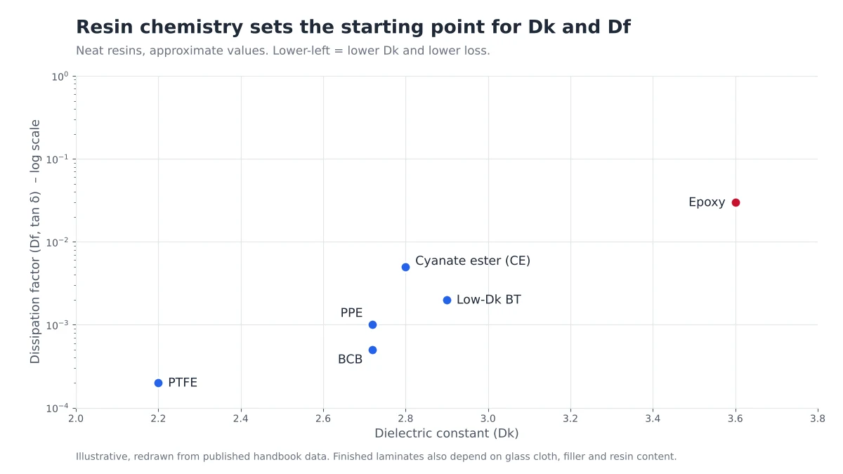
Every laminate datasheet leads with two numbers, the dielectric constant (Dk) and the dissipation factor (Df). Both start life in the resin. Before glass cloth, filler or copper foil enter the picture, the chemistry of the resin system has already decided how easily the material polarizes under an electric field, and therefore how fast signals travel and how much energy is lost along the way.
This guide compares the six resin families you will meet when specifying a PCB laminate (epoxy, BT, PPE, cyanate ester, polyimide and PTFE), explains why they behave differently, and shows how to match a family to your design instead of chasing the lowest Dk on paper.
How Resin Chemistry Sets Dk and Df
Dk describes how strongly a material polarizes when an electric field is applied, and Df describes how much of the field's energy is lost as heat while the molecules keep reorienting. Chemical groups that polarize easily, such as the hydroxyl groups formed when epoxy cures, push both values up. Resin developers therefore lower Dk and Df by removing or reducing those easily polarized structures. That is the logic behind low-polarity systems such as PPE and fluoropolymers like PTFE.
A finished laminate is not pure resin. It is a composite of resin, woven glass and, in many low-loss grades, ceramic filler. Cured epoxy sits at roughly Dk 3.45, while E-glass is around Dk 6.2, so the glass pulls the blend upward. More resin means a lower laminate Dk; more glass means a higher one. This is why the same resin family can show different Dk values on different glass styles, and why the resin choice sets the baseline rather than the final number.
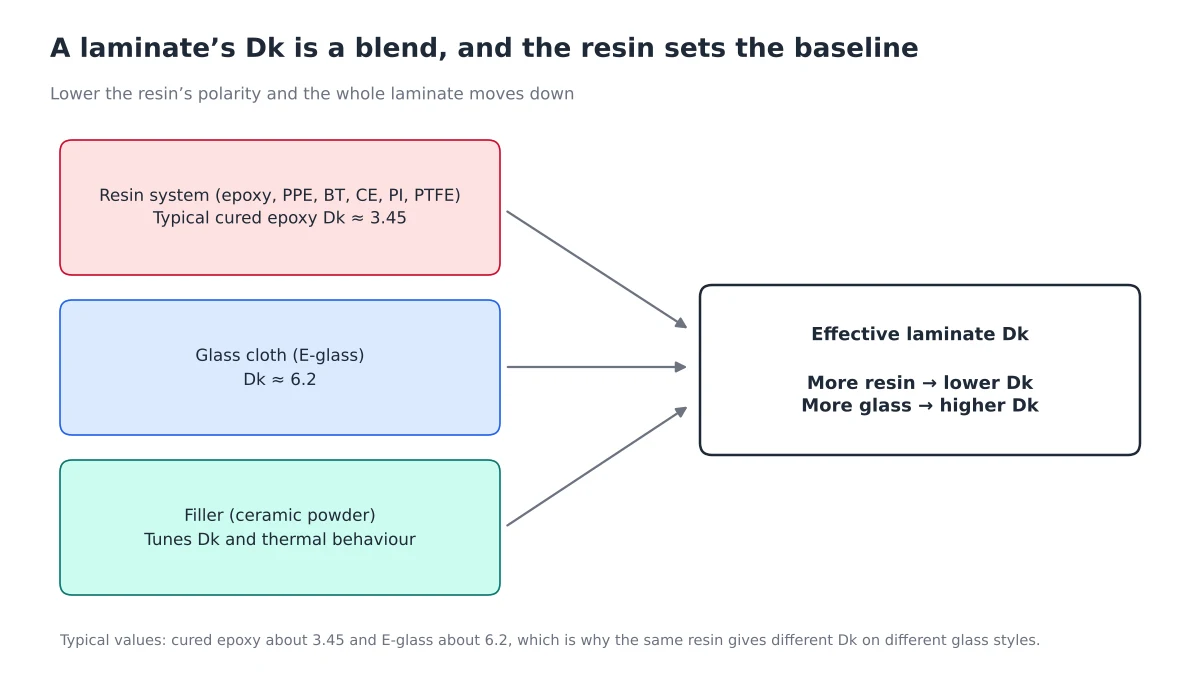
Resin sets the baseline; glass cloth and filler shift the finished laminate's Dk up or down.
The Six Resin Families at a Glance
| Resin family | Electrical position | Heat and reliability | Processing and cost | Typical use |
|---|---|---|---|---|
| Standard and modified epoxy (FR-4 family) | Standard FR-4 runs at roughly Df 0.018–0.025 at 10 GHz. Modified low-loss epoxy grades lower it noticeably. | From Tg 130°C standard grades to Tg 190°C for low-loss epoxy such as Isola FR408HR. | Easiest to process and lowest cost. | General boards, impedance-controlled digital, cost-driven high-speed. |
| BT (bismaleimide triazine) | Low-Dk grades exist, a step better than epoxy. | Strong thermal and dimensional stability, and top-ranked for resistance to CAF (ion migration). | Costs more than epoxy; less common as a bare-board laminate. | IC package substrates, high-reliability boards. |
| PPE (polyphenylene ether), often blended with epoxy or hydrocarbon | Low Dk and low Df. Panasonic Megtron 6 is a PPE-based system. | Good Tg and moisture resistance. | Close to FR-4 in fabrication, at a moderate premium. | Servers, routers, switches, multi-gigabit backplanes. |
| Cyanate ester (CE) | Low Dk and Df, between PPE and PTFE on loss. | High heat resistance, but the weakest moisture resistance in the group. | Higher cost; needs moisture control in handling. | Demanding aerospace and high-end electronics. |
| Polyimide (PI) | Not a low-loss choice. NextPCB lists Ventec VT-901 polyimide at Dk 4.05 and Df 0.012. | Best heat resistance: the same VT-901 is rated Tg 250°C. | More difficult to process; higher cost. | High-temperature, aerospace, flexible circuits. |
| PTFE (fluoropolymer) | Lowest Dk and Df. Rogers RT/duroid 5880 is Dk 2.20 and Df 0.0009 at 10 GHz. | Hydrophobic and very stable in humid conditions. | Hardest to process (plasma treatment is needed for hole walls) and the most expensive. | RF, microwave, millimeter-wave. |
Reading the Trade-Offs: A Relative Ranking
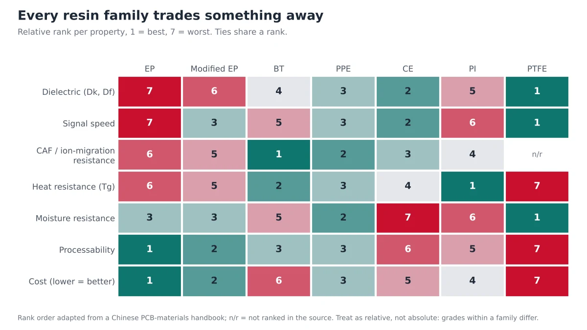
The chart below ranks the seven resin systems (standard epoxy, modified epoxy, BT, PPE, CE, PI and PTFE) property by property, with 1 as best. The order comes from a classic laminate handbook comparison, so treat it as relative guidance: individual grades within a family can differ.
Three patterns stand out.
- The electrical leaders pay for it elsewhere. PTFE and CE rank first and second on dielectric performance, but they sit near the bottom on processability and cost.
- PPE is the balanced option. It ranks in the top three for dielectric performance, signal speed, CAF resistance and moisture resistance, while staying mid-table on cost and processability. That balance is why PPE-based laminates dominate multi-gigabit digital boards.
- BT and PI are reliability materials. BT leads on CAF resistance and is second on heat resistance; PI leads on heat. Neither is chosen for low loss.
Dk and Df Do Different Jobs
Resin choice affects two separate things, and they are easy to conflate.
- Dk governs speed and impedance. For a given trace, characteristic impedance falls as Dk rises. A lower-Dk resin lets you use thinner dielectric layers for the same impedance, which brings signal layers closer to their reference planes, allows more routing layers in the same board thickness and shortens signal paths.
- Df governs loss. Dielectric loss grows with both frequency and Df, so loss-limited links (long channels, multi-gigabit rates) depend on Df far more than on Dk.
For the difference between high-speed and high-frequency designs, and why each emphasizes different properties, see High-Speed vs High-Frequency PCBs. For why the Dk printed on a datasheet rarely matches the Dk in your finished board, read Datasheet Dk vs Real Dk.
Choosing a Resin Family for Your Design
Moderate-speed digital with controlled impedance
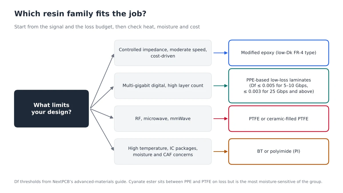
A modified epoxy in the FR-4 family usually covers it at the best price-to-performance ratio. If thermal reliability is the real concern, compare grades in High-Tg PCB vs Standard FR4 and the FR-4 material guide.
Multi-gigabit digital
NextPCB's advanced-materials guidance puts the Df target at 0.005 or lower for 5–10 Gbps links and 0.003 or lower for 25 Gbps and above. PPE-based laminates are the typical answer. See Panasonic Megtron 6 guide and Isola FR408HR vs Megtron 6 for side-by-side grade comparisons.
RF, microwave and millimeter-wave
PTFE-based laminates give the lowest loss and the most stable Dk. They are also the hardest to fabricate, so many designs use them only on critical signal layers and keep FR-4 elsewhere. See Rogers PCBs, Teflon PCBs and Rogers vs FR4.
High temperature, packages and moisture or CAF concerns
BT and polyimide trade electrical performance for thermal and dimensional stability. Choose them when the operating environment or the assembly process, not the signal, sets the requirement.
Whichever family you pick, aim for the lowest-cost option that meets your electrical, mechanical and thermal needs. Over-specifying inflates cost; under-specifying with a cheaper substitute risks failures that are expensive to find after assembly.
What to Specify to Your Fabricator
- The exact laminate and prepreg grade. "FR-4" or "high-speed material" is not a specification; brand and model are.
- The frequency or data rate the Dk and Df must hold at. Values are measured at specific frequencies and shift between them.
- Your target impedance and dielectric thickness intent, so the fabricator can choose cores and prepregs to hit them. Pull verified build-ups from NextPCB's impedance-control stackups.
- Halogen-free requirements where regulations or customers demand them.
- Hybrid intent if you plan to mix families, for example a low-loss laminate on signal layers and standard FR-4 elsewhere.
Browse the laminates NextPCB supports, with Dk, Df and Tg side by side, in the advanced PCB materials database.
FAQ
Which resin has the lowest Dk and Df?
PTFE. For example, Rogers RT/duroid 5880 is rated at Dk 2.20 and Df 0.0009 at 10 GHz, among the lowest values available in a reinforced laminate.
Is PPE better than epoxy for high-speed boards?
PPE-based laminates generally offer lower loss than epoxy while remaining close to FR-4 in fabrication. They also cost more. Modified epoxy is often sufficient at lower data rates, so match the material to your loss budget.
Why is BT resin used in IC packages rather than ordinary boards?
BT combines thermal and dimensional stability with strong resistance to ion migration (CAF), which suits package substrates. Its cost and the availability of cheaper FR-4 options keep it uncommon on general-purpose boards.
Does a lower Dk always mean lower signal loss?
No. Dk sets signal speed and impedance; Df sets dielectric loss. A material can have a low Dk and still be lossy, so check both values and the frequency they were measured at.
Can I mix resin families in one PCB?
Yes. Hybrid stackups, such as low-loss laminate on signal layers and FR-4 on power and ground layers, are widely used to control cost. Confirm with your fabricator which combinations they support and how the layers will be bonded.
Choose Your Laminate With an Engineer Who Builds It
Share your stack-up, data rate and target impedance, and the NextPCB engineering team will review the laminate choice and confirm manufacturability before you order.
- Compare laminates in the advanced materials database
- Pull verified impedance-control stackups
- Questions about a specific grade: support@nextpcb.com