NextPCB Capabilities
 PCB Assembly
 Process Capabilities

 Quality
 Drills & Throughplating
 Factory & Certificate



Datasheet Dk vs Real Dk: What Shifts Dielectric Constant and Dissipation Factor in a Real PCB
A laminate datasheet gives you one Dk and one Df. Your finished board does not behave like one number. The value on the datasheet is the result of a specific test, at a specific frequency, on a specific sample. Your board has its own frequency content, glass style, resin content, copper roughness, operating temperature and humidity.
This guide explains what moves Dk and Df between the datasheet and the board, how much it matters for impedance and loss (with the numbers worked out), and which Dk to put into your impedance calculator.
What the Datasheet Dk Actually Is
Dk (relative permittivity, also written εr) sets how fast a signal travels and what impedance a trace has. Df (dissipation factor, also called loss tangent or tan δ) sets how much signal energy the dielectric absorbs. Both are measured, not assumed, and the datasheet reports a single result.
That result depends on the test method and frequency stated beside it. For example, Rogers RT/duroid 5880 is specified at Dk 2.20 ±0.02 and Df 0.0009 at 10 GHz. Many datasheet values are also measured after conditioning the sample at 23 °C and 50% relative humidity, a lab condition your board will rarely stay in.
Laminate makers often publish a design Dk as well: the value intended for impedance calculations, which can differ from the test-method value. For RT/duroid 5880 the design Dk is 2.20, and it can be used directly for impedance. For epoxy-glass laminates, makers commonly publish Dk per construction (glass style and resin content), because one number is not enough.
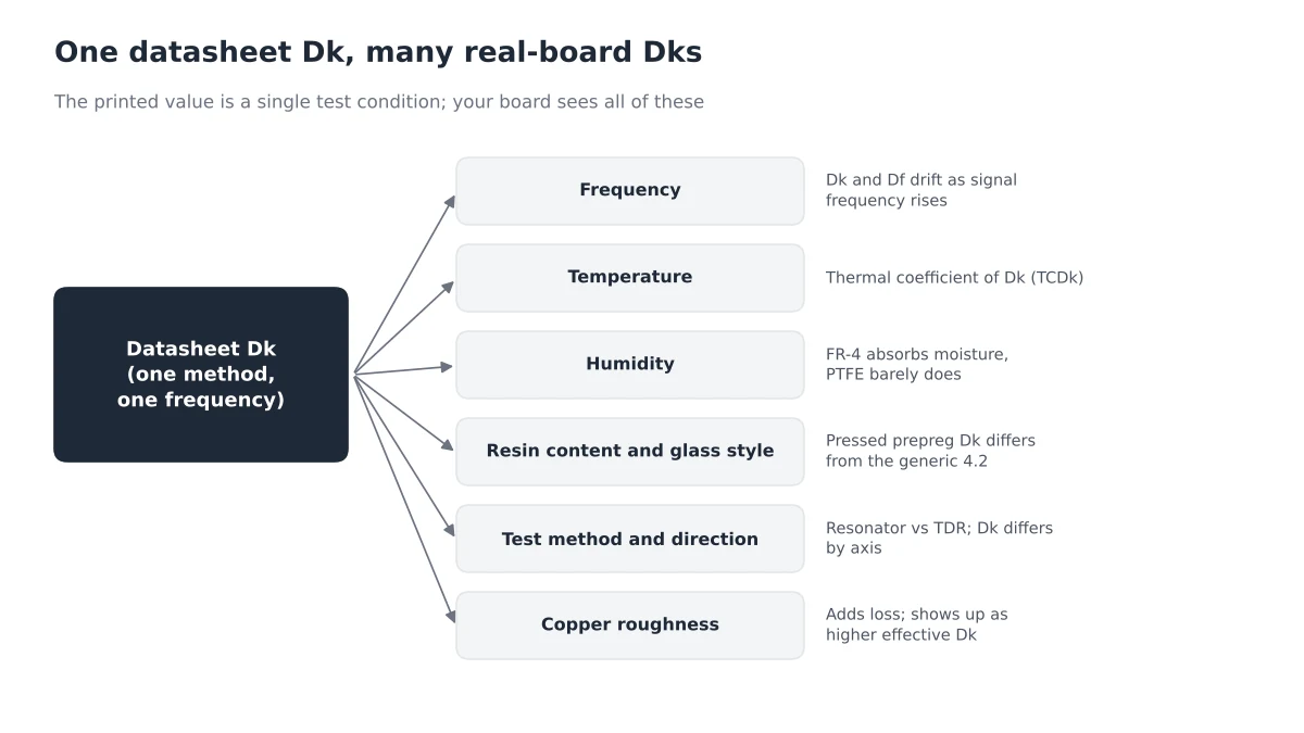
Six Things That Move Dk and Df
| Factor | What happens | What to do |
|---|---|---|
| Frequency | Dk usually drifts down slowly as frequency rises, while Df can drift up. Values are only valid near the test frequency. | Compare materials at the same frequency, and use data near your signal's bandwidth. |
| Temperature | Each material has its own thermal coefficient of Dk (TCDk). RT/duroid 5880, for instance, is listed at −125 ppm/°C. | Check TCDk for timing- or phase-sensitive designs and wide temperature ranges. |
| Humidity | Absorbed water raises both Dk and Df. NextPCB's high-speed FR-4 specification lists water absorption of 0.15% or less; RT/duroid 5880 is listed at 0.02%. | Check moisture absorption, and choose hydrophobic materials where the environment is humid. |
| Resin content and glass style | Resin has a lower Dk than glass, so more resin means lower Dk. NextPCB's stackup guide lists nominal Dk of 4.0 for 106 and 1080-type prepregs and 4.2 for 2313 and 2116. Prepreg also flows during lamination, so its final thickness and Dk depend on the copper distribution around it; cores are more stable. | Use the Dk of the pressed construction, not a generic FR-4 value. |
| Test method and direction | Resonator methods and time-domain methods measure different things, and Dk differs between in-plane and through-thickness directions. | Know which method produced the number and whether it matches how you will use it. |
| Copper roughness | Rough copper adds conductor loss, which time-domain and phase-based extractions read as a higher effective Dk. | Specify smooth (low-profile) foil for the fastest links, and expect a small gap between lab and board values. |
How Much Does a Dk Error Move Impedance?
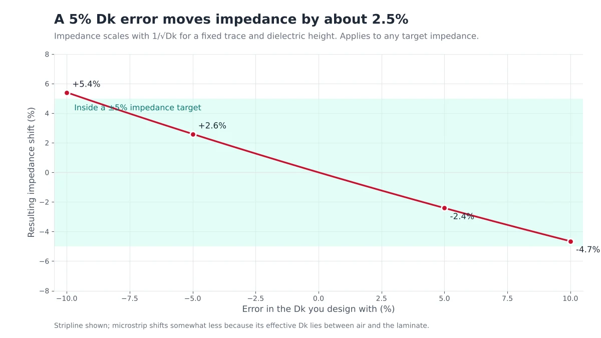
For a fixed trace geometry and dielectric height, characteristic impedance is proportional to 1/√Dk. That makes the effect of a Dk error easy to calculate. A 5% error in the Dk you design with shifts impedance by roughly 2.5%.
| Dk error | Impedance shift | 50 Ω target becomes | 100 Ω target becomes |
|---|---|---|---|
| −10% | +5.4% | 52.7 Ω | 105.4 Ω |
| −5% | +2.6% | 51.3 Ω | 102.6 Ω |
| +5% | −2.4% | 48.8 Ω | 97.6 Ω |
| +10% | −4.7% | 47.7 Ω | 95.3 Ω |
Tight impedance targets, such as ±5%, leave little room. A 5% Dk assumption error alone can use up about half of that budget before etch tolerance and dielectric thickness variation are counted. Dk also sets propagation speed (inversely proportional to √Dk), so it affects timing and skew in matched pairs and buses.
Thickness is the other half of the impedance equation. Pressed dielectric thickness deviates from nominal, as covered in the cost-driven high-speed stackup and impedance guide.
Df: Where the Loss Comes From
Dielectric loss in dB per inch is approximately 2.3 × frequency (GHz) × √Dk × Df. It grows linearly with frequency, and Df sets the slope.
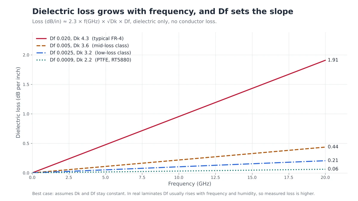
At 10 GHz over a 10-inch trace, the dielectric alone costs about:
- 9.5 dB for a typical FR-4 (Df 0.020, Dk 4.3)
- 2.2 dB for a mid-loss class laminate (Df 0.005, Dk 3.6)
- 1.0 dB for a low-loss class laminate (Df 0.0025, Dk 3.2)
- 0.3 dB for PTFE such as RT/duroid 5880 (Df 0.0009, Dk 2.2)
These figures exclude conductor loss, copper roughness, vias and connectors, all of which add to the total. They also assume Df is constant, which flatters the result, because Df typically rises with frequency and humidity. For low-loss grade comparisons, see Isola FR408HR vs Megtron 6 and high-speed PCB materials for AI servers. For how resin chemistry sets the baseline Df in the first place, read Why Resin Chemistry Sets Dk and Df.
Which Dk Should You Use in Your Impedance Calculator?
Avoid hard-coding "FR-4 = 4.2" or "4.5". Work through these five checks instead.

- Read the test method and frequency. Know whether the value came from a resonator, a stripline test or a time-domain method, and at what frequency.
- Match it to your signal. Use the Dk at a frequency that reflects your signal. A rough guide to the significant frequency of a digital edge is 0.35 divided by the 10–90% rise time, so a 100 ps edge points to about 3.5 GHz.
- Use the construction-specific Dk. Take the Dk for the actual glass style and resin content, not a generic laminate value. NextPCB's core, prepreg and copper foil guide lists nominal cores and prepregs with their Dk.
- Allow for humidity and temperature. Check TCDk and moisture absorption, especially for boards in humid or wide-temperature environments.
- Confirm with the fabricator. Ask for pressed stackup data and an impedance test coupon, or start from NextPCB's impedance-control stackups, built from the real material set.
Humidity and Temperature in the Field
Lab values assume controlled conditions. Your board will see humid summers, thermal cycling and, in assembly, several reflow passes. Materials that absorb moisture, such as FR-4, can drift toward higher Dk and Df in service, while hydrophobic materials such as PTFE hold their values far better.
Fabrication quality also matters. Poor lamination can lead to delamination or voids, which let moisture in and degrade electrical performance that looked fine on the datasheet. When a design is sensitive to Dk stability, review the material's moisture absorption and TCDk alongside its headline Dk and Df, and discuss the lamination of high-viscosity low-loss resins with your fabricator.
FAQ
Is the datasheet Dk the value I should use for impedance?
Not by default. Use the maker's design Dk for your construction and frequency range, and then confirm against your fabricator's pressed stackup data.
Why does the same FR-4 have different Dk in different stackups?
Because the glass style and resin content differ. Resin has a lower Dk than glass, and prepreg flows during lamination, so the pressed Dk changes with the construction and the copper distribution around it.
Does Dk change with frequency?
Usually yes, by a small amount that depends on the material. This is why datasheets state the frequency at which Dk and Df were measured, and why comparing values taken at different frequencies can mislead.
Which matters more, Dk or Df?
They do different jobs. Dk sets impedance and propagation speed, and Df sets dielectric loss. Short, impedance-critical links lean on Dk; long, fast channels lean on Df.
How can I verify the real Dk on my board?
Ask your fabricator for impedance test coupon results measured with time-domain reflectometry, and compare them with the stackup used in your calculations. Adjust trace width or dielectric thickness if they disagree.
Get Your Stackup and Impedance Checked Before You Order
Send your stack-up, material and target impedance, and the NextPCB engineering team will check the numbers against real pressed-stackup data.
- Pull verified impedance-control stackups
- Compare laminates in the advanced materials database
- Questions about a design: support@nextpcb.com