Table of Contents
- The Uncomfortable Truth of Modern PCB Design
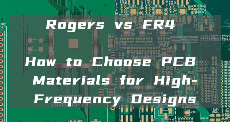
- 1. The Contenders: Defined
- 2. The Technical Showdown: Dk and Df
- 3. Deep Dive: Types of High-Frequency Materials
- 4. The Decision Matrix: When to Select Rogers
- 5. Cost Optimization: The Hybrid Stackup Solution
- 6. Ordering and Specification Guide
- 7. FAQ on High-Frequency PCB Materials
- 8. The Final Word: Make a Calculated Decision
Introduction (The Uncomfortable Truth of Modern PCB Design)
For decades, FR4 has been the default and most economical answer for printed circuit boards. However, the market is rapidly shifting. Driven by consumer demands for faster internet connections, high-definition mobile video, and the proliferation of IoT devices, PCBs must now meet high-frequency performance requirements while simultaneously supporting high-speed digital data transfer. Commercial applications like 5G infrastructure, big data centers, and IoT, alongside increasing personal usage, are constantly pushing the limits of digital communication systems. As a result, the bandwidth requirements for high-speed digital systems are effectively doubling roughly every three years.
The moment a project introduces signals over 5 GHz, designers and procurement managers are forced to confront the Rogers vs. FR4 dilemma. This choice is not just a technical specification; it represents a significant cost negotiation. Specialty laminates like Rogers are significantly more expensive than FR-4, and in prototyping they can easily double the PCB cost depending on thickness, copper type, and availability.
This guide provides a calculated, professional framework to help you decide when the cost of specialized high-frequency materials is truly justified.
1. PCB Material Contenders: Defining FR4 and Rogers for High-Frequency Design
To make an informed decision, we must start with a precise understanding of the two materials' fundamental makeup.
1.1 What is Standard & High-Tg FR4? (The Industry Standard)
FR4 is a composite of woven glass fabric and epoxy resin. It provides excellent mechanical strength, good processability, and standard electrical insulation, making it the bedrock of the PCB industry.
- Best for: Digital circuits, low-frequency analog, LED boards, and general-purpose electronics.
- NextPCB Standard: For demanding industrial and automotive builds, NextPCB supports High-Tg FR-4 options (e.g., KB TG170 and Shengyi high-Tg series), helping improve resistance to warpage and delamination during lead-free reflow and thermal cycling.
Need a comprehensive breakdown of FR4 grades and capabilities?
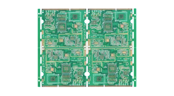
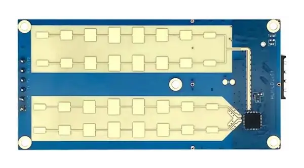
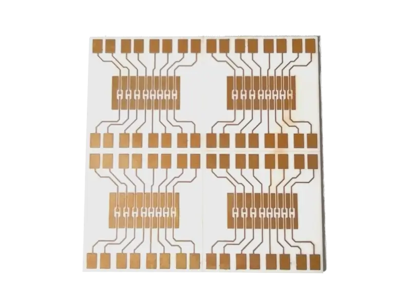
Pictured above: A NextPCB 12-Layer Automotive PCB using Shengyi TG170 laminates. High-Tg FR4 is the robust, cost-effective choice for complex boards where thermal stability, not extreme frequency, is the primary concern.
1.2 What is a Rogers PCB Material? (The High-Frequency Specialist)
Rogers Corporation specializes in high-frequency laminates. These materials use non-epoxy bases, typically ceramic-filled PTFE (Teflon) or specialized hydrocarbon systems. These chemical differences are what yield the critical stability required for high-frequency signals.
- Best for: RF (Radio Frequency), Microwave designs, Radar sensing, and telecommunications applications operating above 6 GHz.
Ready to dive deep into Rogers material grades and RF applications?
1.3 Overall Comparison: FR4 vs. Rogers at a Glance
This table summarizes the core differences that impact design and cost decisions.
| Feature |
Standard/High-Tg FR4 |
Rogers-Class Laminates |
| Base Material |
Woven Glass + Epoxy Resin |
Ceramic/PTFE (Teflon) or Hydrocarbon |
| Typical Dk |
High (Approx. 4.3–4.5) |
Low (Approx. 2.2–3.5) |
| Dk Stability |
Varies significantly with temperature/frequency |
Very stable and consistent |
| Signal Loss (Df) |
High (Df ≈ 0.02) |
Very Low (Df ≈ 0.002–0.004) |
| Cost (Relative) |
Low (Industry standard baseline) |
High (Significantly more expensive) |
| Processability |
Easy (Standard drilling and etching) |
More Difficult (Requires specialized handling for PTFE) |
2. The Technical Showdown: Dk and Df
While the production processes for high-frequency and standard PCBs share similarities, the core difference lies entirely in the raw materials’ properties. High-frequency and high-speed PCBs rely on specialized laminates characterized by a low Dielectric Constant (Dk) and a low Dissipation Factor (Df). These two parameters are paramount for ensuring the speed and quality of signal transmission.
The insistence on using Rogers or similar materials is rooted in how these two physics principles affect signal integrity at high speeds. Let's break down the technical argument.
A. Dissipation Factor (Df) – The Signal Attenuator
Df measures how much signal energy is absorbed by the material and converted into heat. This loss is known as attenuation.
- Standard FR4 (Df ≈ 0.02): Has a relatively high loss. At high frequencies, this loss significantly attenuates the signal, especially over longer traces.
- Rogers: Rogers-class RF laminates typically deliver Df around ≈ 0.002–0.004 at 10 GHz (depending on grade), far lower than standard FR-4. This minimal resistance is non-negotiable for critical signals.
B. Dielectric Constant (Dk) Stability
The Dk doesn't just need to be a low number; it needs to be consistent. Dk is the primary factor used to calculate trace impedance (50 Ω or 75 Ω).
- FR4: The Dk often shifts significantly with temperature and frequency. This causes the impedance you calculated in your simulation to drift in the real world, leading to reflection issues.
- Rogers: Rogers materials offer a much more stable Dk (e.g., RO4350B is around Dk ≈ 3.48 @10 GHz), helping impedance stay closer to what you designed.
3. Deep Dive: Types of High-Frequency Materials
Understanding the chemical category of the high-frequency material helps predict processing difficulty and final cost.
Thermoset Hydrocarbon Laminates (e.g., Rogers RO4000® Series)
- Key Trait: Ceramic-filled hydrocarbon systems that are rigid and engineered to process similarly to standard FR4, often making them more cost-effective to manufacture than pure PTFE for many RF builds.
- Best for: Cost-sensitive RF designs and hybrid stackups.
PTFE (Teflon) Laminates (e.g., Rogers RO3000® Series)
- Key Trait: PTFE-based materials offer the lowest loss and best stability. However, they are mechanically soft and often require specialized manufacturing steps and tighter process control (e.g., drilling considerations, surface preparation) compared to FR4-like systems.
- Best for: Critical mmWave applications and high-performance antennas.
Polyphenyl Ether (PPO/PPE) and Modified Resin Systems (High-Speed Digital)
In the push for faster data rates, material developers sought an alternative to pure PTFE that retains strong electrical performance while offering better processability for complex builds.
- Polyphenyl Ether (PPO or PPE) has emerged as a key solution. Its dielectric performance is often positioned as a strong option for Very Low Loss and Ultra Low Loss high-speed digital applications, while remaining more fabrication-friendly for multi-layer and HDI designs.
- Key Products: Popular examples of modified PPO resins include Panasonic's M6 and M7N, and ITEQ's IT968 and IT988GSE.
- The Hybrid Approach: To address the processing challenges of pure PTFE in high-layer count and HDI boards, developers blend PPO-based systems with hydrocarbon resins to balance electrical performance and manufacturability. For example, ITEQ’s high-frequency portfolio (including IT-88GMW, IT-8300GA, etc.) uses this type of modified resin approach to meet high-frequency demands while improving processability.
Manufacturing Consideration: Copper Profile
At high frequencies, the signal current flows predominantly near the copper surface (skin effect). As frequency pushes into ≈ 20 GHz+, copper surface roughness becomes a major contributor to loss. Specifying low-profile copper or rolled copper is essential for minimizing attenuation in these extreme cases.
> See NextPCB High-Frequency PCB Materials
4. The Decision Matrix: When to Select Rogers
This scorecard provides a structured approach to material selection. If your project parameters align with two or more points in the right-hand column, the technical risk of using FR4 becomes unacceptable.
| Feature |
Stick with FR4 (Standard or High-Tg) |
Switch to Rogers (High Frequency) |
| Operating Frequency |
< 3 GHz (Generally workable)
3–6 GHz (Short traces, tight loss budget check) |
~6 GHz+ (Often justified)
mmWave (Typically required) |
| Signal Trace Length |
Short runs (< 2 inches / 50mm) |
Long runs (Signal attenuation is the main concern) |
| Impedance Tolerance |
± 10% is acceptable |
± 5% or tighter is required |
| Thermal Requirement |
High operating temp / Heavy current (Use High-Tg FR4) |
Extreme, rapid temp cycling (Rogers often offers better Z-CTE) |
| Key Application |
Microcontrollers, Power Supply, Standard IoT |
Radar, Phased Array Antennas, RF Power Amplifiers |
> Dive in PCB Thermal Design Basics (1): Substrate Material Selection
Clarification on High-Tg FR4
If your primary concern is high heat, high current, or repeated thermal cycling stress, High-Tg FR4 is the correct, cost-effective solution. The decision to use Rogers is driven by frequency performance, not primarily by thermal endurance.If your design is dominated by heavy current delivery (power conversion, motor drives, high-power rails), a thick copper PCB is often a more direct solution than changing the laminate alone.
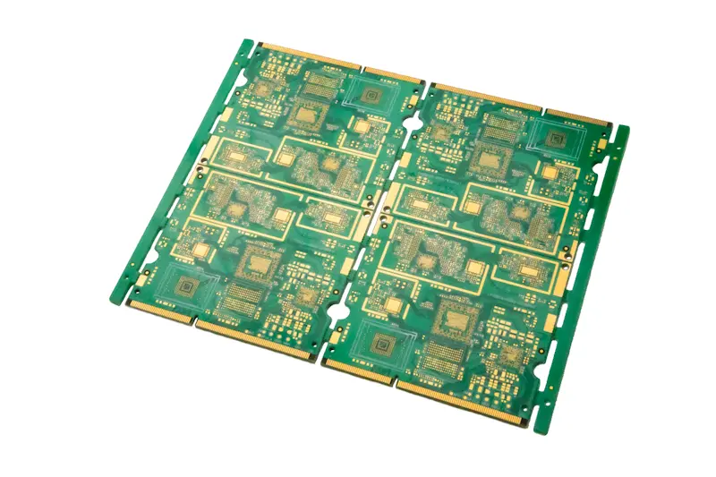
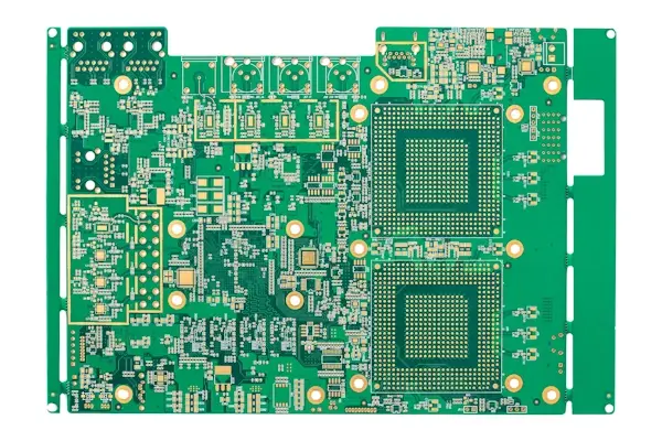
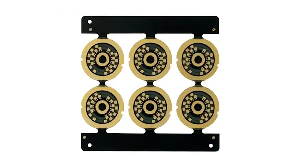
Pictured: 8-Layer Consumer Electronics PCB with Kingbrother TG170. This is the cost-effective champion for boards that require robust thermal durability but operate at standard digital speeds.
5. Cost Optimization: The Hybrid Stackup Solution
If you require high-frequency performance but cannot absorb the full cost of an all-Rogers build, strategic cost optimization is necessary. This is where real cost-saving engineering begins.
We often recommend the use of the Hybrid Stackup.
- Principle: Construct the board using Rogers material for the critical outer layers where RF signal traces reside. Use reliable, low-cost High-Tg FR4 for the inner power, ground, and mechanical structure layers.
- Advantage: You achieve the signal integrity of Rogers where it matters, while benefiting from the lower cost and mechanical stability of FR4 for the bulk of the board.
Note on Manufacturability (DFM): Hybrid boards require precise lamination cycles to manage the different Coefficients of Thermal Expansion (CTE) of the two materials. NextPCB's engineering team is prepared to verify and manufacture these complex mixed-material stackups (e.g., RO4350B + FR4).
Have an Engineer Review My Stackup Quick Check with Our Online Gerber Viewer
6. Ordering and Specification Guide
To ensure a smooth manufacturing process and accurate quotation, professional material specifications are crucial. When submitting your design, be specific about the following parameters:
| Requirement |
Specification Details to Include |
| Material Name |
Rogers RO4350B or Hybrid Stackup (RO4350B + Shengyi FR4) |
| Dielectric Thickness |
Exact thickness required for impedance calculation (e.g., 0.020" or 0.508mm) |
| Copper Type |
Specify Low Profile Copper for designs pushing ~20 GHz+ |
| Reliability Class |
IPC Class 2 (standard) or Class 3 (high reliability) > IPC Class 2 vs. IPC Class 3 |
FAQ on High-Frequency PCB Materials
This section addresses the most common questions engineers and procurement specialists ask when facing the FR4 vs. Rogers material choice.
Q1: What is the primary operational difference between FR4 and Rogers for my signal?
A: The difference is signal loss and stability. Think of FR4 as having high electrical friction (Df ≈ 0.02); your signal loses power rapidly, making it unsuitable for long traces or frequencies above ≈ 5 GHz. Rogers materials have extremely low friction (Df ≈ 0.003), allowing the signal to travel faster and maintain integrity over distance.
Q2: Can I use High-Tg FR4 for my high-frequency design?
A: Only if your frequency requirement is moderate (< 3 GHz) and your trace lengths are short. High-Tg materials are designed for thermal reliability (withstanding high heat and reflow cycles), not electrical performance. They are great for power supplies and automotive electronics, but they do not solve the signal loss (Df) problem inherent in epoxy-based systems.
Q3: Why is Copper Roughness so critical at high frequencies?
A: At frequencies ≈ 20 GHz and above, the signal current flows predominantly near the copper surface (skin effect). Rough copper surfaces (common on standard FR4) disrupt this flow, acting like "speed bumps" and causing significant signal attenuation. Specifying low-profile copper on high-frequency laminates is essential to reduce this loss.
Q4: How much more expensive are Rogers materials compared to FR4?
A: Rogers laminates are categorized as specialty materials and are significantly more expensive than FR4. For prototyping, they can easily double the total PCB cost depending on the specific grade (e.g., PTFE is costlier than hydrocarbon systems), thickness, and availability. This is why utilizing Hybrid Stackups (Rogers only on critical layers) is a popular strategy to manage budget while meeting performance needs.
Q5: What is a Hybrid Stackup and when should I consider it?
A: A Hybrid Stackup involves mixing two different materials (e.g., Rogers RO4350B for the outer RF layers and High-Tg FR4 for the inner power/ground layers) within the same board. You should consider it when:
- You have critical RF circuits only on the surface layers.
- You need to reduce manufacturing cost compared to an all-Rogers board.
- You require the mechanical stability of FR4 for high-layer count builds.
The Final Word: Make a Calculated Decision
The goal of any well-engineered design is to achieve required reliability without incurring unnecessary waste. You now have the full professional context: the technical why (Dk/Df), the budgetary how (Hybrid Stackups), and the reliability check (High-Tg).
Our recommendation is always: Prioritize the signal, then optimize the cost.
Whether your final solution requires an exotic Rogers laminate or a robust Shengyi High-Tg build, NextPCB's engineering team is prepared to review your stackup and ensure manufacturability before the first copper trace is laid.
Ready to make the material switch without the struggle?
About the Author
Lolly Zheng- Sales Account Manager at NextPCB.com
Four years of proven sales experience across electronic components and PCBA industries, with strong expertise in key account acquisition, customer relationship management, and contract negotiations. Focused on driving revenue growth through strategic client development and solution-based selling. Experienced in expanding high-value accounts, securing long-term partnerships, and consistently exceeding sales targets in competitive markets.


 NextPCB Capabilities
 PCB Assembly
 Layer Buildup
 SMD-Stencils
 PCB Design-Aid & Layout
 Mechanics
 Surface
 Quality
 Drills & Throughplating
 Factory & Certificate