Stackup design is an important part of multilayer PCB design and includes the planning of everything from the number and content of copper layers, dielectric materials and thicknesses, the lamination structure and the configuration of vias that make up the printed circuit board. Effective stackup planning is fundamental to high-speed design and for building an effective signal integrity strategy.
With more and more manufacturers offering cost-effective pooling services, is it still possible to achieve controlled impedance without increasing costs? The answer is a resounding yes, and here we tell you how.
Fixed stackups and effective production control are your best friends
For multilayer PCBs, each fabricator has their preference of lamination structures for different layer counts and board thicknesses. Lamination structure typically follows the same rules; an even number of copper layers, symmetrical relative to the center, alternating between cores and prepregs, etc., but the precise configuration and thicknesses of the dielectrics are at the discretion of the fabricator.
Take 4-layer PCBs for example. The three structures below are completely acceptable stackups commonly used in the industry, and a fabricator can choose any one to be their go-to "standard stackup".
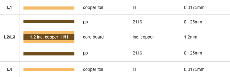
NextPCB 04161H01-2116: 4-layer 1.6mm PCB stackup with 2116 prepreg

NextPCB 04161H02-1080: 4-layer 1.6mm PCB stackup with 1080 prepreg
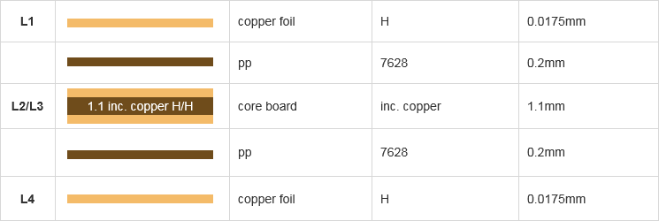
NextPCB 04161H03-7628: 4-layer 1.6mm PCB stackup with 7628 prepreg
Why standard stackups matter
From a cost and efficiency standpoint, it makes sense to have a default stack-up that is used for 99% of consignments with the same number of layers and final board thickness, which is why it is common for quickturn services to have a default stack-up. Compare this with traditional non-pooling services, where each consignment is produced individually. There is no mixing of boards, and it is common practice for high-speed designers to specify their own preferred stackup that works with their design's transmission line geometries.
While the choice of standard stackup may have little impact in terms of manufacture, high-speed designers will, of course, be familiar with the impact this has on their designs, and the ability to reliably reproduce the same structure can make or break a partnership. If designers want to take advantage of the substantial cost savings of quickturn PCBs without compromising signal integrity, prior knowledge of the PCB's lamination structure and substrate properties is crucial. A manufacturer who provides this transparency and support demonstrates an understanding of signal integrity goals, essential for long-term collaboration and success. You can instantly view our standard lamination structures to match your design requirements.
NextPCB's Stackup Offerings
Rather than a single standard stackup, NextPCB offers over 40 lamination structures at no additional cost with the standard PCB service. Choose common stackups from 4 to 10 layers, including pseudo-layer boards, directly from the order form and have them managed through our MES for guaranteed consistency and repeatability.
New Feature: To make finding the right lamination structure even easier, we have launched a dedicated Impedance Control Stackups Query Page. You can now browse, filter, and review our complete database of standard and advanced stackups before you even begin routing!
Specializing in reliable multilayer PCB fabrication and assembly, NextPCB understands the importance of impedance control and offers support for a wide spectrum of customization needs, including stackup selector/impedance calculator, assisted impedance control and verification, and custom stackups for advanced requirements.
Recommended Reading: Choosing High-Speed PCB Stackups from 4 to 10 Layers
Recommended Standard Stackups
Below are our recommended lamination structures and stackups to help you decide on the best structure for your high-speed or high-frequency design.
Stackup materials and layers recap
Core: Also known as copper-clad laminates (CCL), cores are rigid pre-cured laminates typically made of FR-4 fiberglass dielectric material with copper foil 'cladded' on both sides. A core is essentially a two-layer board before etching, and for multilayer PCBs, thicknesses typically range from 0.1mm to 0.5mm.
Prepreg: Prepreg or pp (short for pre-impregnated) is a thin weave of glass fibres impregnated with epoxy. Prepreg is used to electrically insulate adjacent cores and copper foils and serves as the adhesive holding the entire board together after curing in a igh-temperatures pressure environment. Codes are given for prepregs of varying weave densities and thicknesses, such as 2116 (0.125mm), 1080 (0.077mm) and 7628 (0.2mm).
Foil: Copper foils are thin sheets of conductive material that usually form the outer circuit layers in a multilayer stackup (i.e. outer layers). For a PCB requiring 1oz final copper thickness, typically a 1/2 oz (H) thick copper foil is used in the stackup, which is electroplated up to 1oz in later steps.
Both cores and prepregs come in various thicknesses, colors, and sizes from manufacturers, with some options being more common than others. By utilizing a few select thicknesses, fabricators can reduce costs and manage stock more efficiently, but at the expense of flexibility. As such, it is important to confirm what materials your manufacturer stocks and understand that not all combinations are possible.
4-Layer PCB Stackups for Impedance Control
Lamination Structure
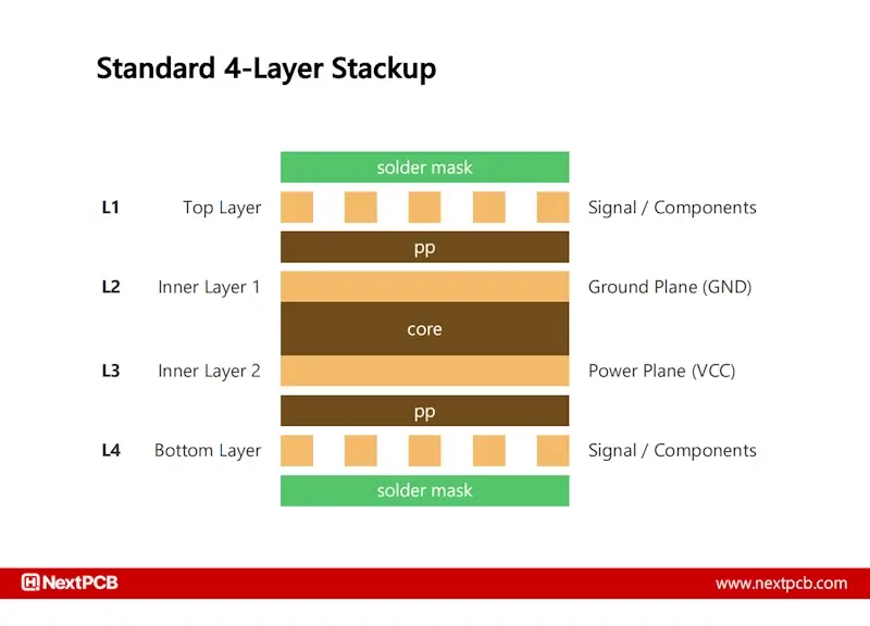
A typical 4-layer lamination structure consists of a core (2-layer board) with a layer of prepreg and copper foil on either side.
The inner layers can be set up as a ground and power reference plane, offering excellent signal return paths and shielding for sensitive signals on the outer layers. In microstrip calculations, H1 and Er1 are the thickness and dielectric constant of the prepreg, respectively. For a target impedance value, the width of the trace decreases with prepreg thickness, as can be seen in the screenshot below. Therefore, thinner prepregs such as 1080 allow for finer traces, ideal for high-density boards and BGA routing. For lower routing densities and higher current requirements, 2116 and 7628 allow for traces 8 to 14 mils in width.
The core thickness is chosen to make up the desired final board thickness and provide sufficient insulation.
NextPCB Available 4-Layer Stackups
| Final Board Thickness |
Prepreg Options |
2116
(0.125mm) |
1080
(0.077mm) |
7628
(0.2mm) |
| 0.6 mm |
✓ |
✓ |
|
| 0.8 mm |
✓ |
✓ |
✓ |
| 1.0 mm |
✓ |
✓ |
✓ |
| 1.2 mm |
✓ |
✓ |
✓ |
| 1.6 mm |
✓ |
✓ |
✓ |
| 2.0 mm |
✓ |
✓ |
✓ |
6-Layer PCB Stackups for Impedance Control
Lamination Structure
The most cost-efficient 6-layer lamination structure uses two cores insulated by a layer of prepreg, and an additional layer of prepreg and copper foil on either side, as with a 4-layer board. The major difference here is that a thin dielectric forms the center of the stackup (between L3 and L4) rather than a core.
You would be forgiven for assuming upgrading to a 6-layer board gives two additional routing layers at the center; however, from an EMC and signal integrity perspective, this is not ideal. The tight coupling between L3 and L4 makes them highly susceptible to crosstalk, and the close proximity to a signal layer can lead to unpredictable impedance variation, making this stackup obsolete for high-speed designs.
A common and more effective practice is to dedicate one layer as a power plane and pair it with an adjacent ground plane, as shown in Figure 2. This creates a low-impedance power distribution network and provides the shielding needed for a proper stripline environment.
> Recommend reading: Best 6-Layer PCB Stackups for Signal Integrity & Impedance Control

Pseudo 8-Layer Stackup (6-Layer Board)
Pseudo (fake) 8-layer stackups offer a solution to the crosstalk issue in the standard 6-layer build-up. Pseudo 8-layer stackups consist of 3 cores, and in the stackup below, the central core has had the cladding completely etched away, leaving behind a thick, rigid dielectric. The purpose of the etched core is simply to increase the dielectric distance from L3 and L4, minimizing crosstalk issues and promoting coupling with L2 and L5.

Why not three full cores?
In order to achieve the thinner outer dielectric thickness, prepreg is often used instead of a thin core. Therefore, following the core-prepreg-core rule, the centre of the board should consist of prepreg layers. Prepregs can be stacked; however, in practice, it is not recommended to stack more than 3 sheets of prepreg together.
7628 is typically the thickest, with a laminated thickness of 0.2mm. Therefore, the maximum dielectric thickness possible with prepreg is 0.6mm, insufficient for 1.2mm and 1.6mm configurations. The use of an etched core instead of stacked prepregs also provides additional mechanical strength during layup.
Regardless of whether the design calls for prepreg or core, PCB fabricators will construct a stackup that satisfies the final dielectric thickness requirements.
NextPCB provides pseudo 8-layer PCB stackups from 1.2mm and above.
Cost of Pseudo 8-layer boards
In the PCB fabrication industry, stackups are defined by the number of cores. Therefore, a 3-core board corresponds to an 8-layer board, even though these boards only consist of 6 copper layers, hence the name 'Pseudo 8-layer boards'. Likewise, expect to pay prices similar to standard 8-layer boards since the processing steps and lamination cycles are the same as 8-layer boards.
NextPCB Available 6-Layer Stackups
| Final Board Thickness |
Prepreg Options |
1080
(0.077mm) |
2116
(0.125mm) |
1080 (8)
(0.077mm) |
2116 (8)
(0.125mm) |
| 0.8 mm |
✓ |
✓ |
|
|
| 1.0 mm |
✓ |
✓ |
|
|
| 1.2 mm |
✓ |
✓ |
✓ |
✓ |
| 1.6 mm |
✓ |
✓ |
✓ |
✓ |
| 2.0 mm |
✓ |
✓ |
✓ |
✓ |
| 2.5 mm |
✓ |
✓ |
✓ |
✓ |
(8) = psuedo 8-layer structure
With the standard 6-layer stackup, broadside striplines should not be attempted between layers 3 and 4. The central prepreg is extremely thin - only 0.103mm in NextPCB's standard stackups. Combined with thickness tolerances, this makes coupling extremely sensitive to manufacturing variation. Thickness is much harder to control compared to trace width. A tiny variation in laminate thickness, that is within manufacturing tolerances, could cause a large shift in impedance.
8-Layer PCB Stackups for Impedance Control
As mentioned, with pseudo-8-layer boards, standard 8-layer boards consist of 3 cores but also have the additional prepreg and copper foils to make up 8 circuit layers. This easily allocates 4 full layers for signal routing, GND/PWR pairs and components on both sides.

NextPCB Available 8-Layer Stackups
| Final Board Thickness |
Prepreg Options |
1080
(0.077mm) |
2116
(0.125mm) |
| 0.8 mm |
- |
- |
| 1.0 mm |
✓ |
- |
| 1.2 mm |
✓ |
- |
| 1.6 mm |
✓ |
- |
| 2.0 mm |
✓ |
- |
| 2.5 mm |
✓ |
- |
How to Choose a Stackup
Determine the number of copper layers for your board and assign the signal layers, references, power-ground pairs etc. You can compare the advantages and disadvantages of common stackup schemes in this guide.
Step 1: Head over to our Impedance Control Stackups Page to quickly query and view the detailed lamination structures (core and prepreg thicknesses) available for your specific layer count and board thickness.
Use NextPCB's Stackup Selector/Impedance Calculator tool to see the possible lamination structures available at no extra cost and calculate the trace widths and spacings for all your transmission lines.
Fill in the board's layer count, thickness and inner and outer copper thicknesses. Then fill in information on the impedance-controlled traces on the PCB and click Calculate. The tool will then tell you which of NextPCB’s common stackups are suitable and the specific trace adjustments required.
Once you've finished the design and are ready to order, you need to specify the intended lamination structure to your manufacturer.
How to Order your Chosen Stackup
You can select your preferred stack-up directly on the NextPCB quotation page. Simply select the relevant number of copper layers, board thickness, and inner and outer copper thicknesses, and the names of the available common stack-ups will appear under Special Process -> Stack up. The default option is No Requirement.

You can also find the stackup selector tool from the quotation page. Here, the tool will use the board settings selected on the order form. Use the tool to verify your impedance settings are correct, then click the checkbox to select the stackup on the order form, and then close the tool.
Note that there are no common stack-ups for the Advanced PCB service and some lesser common board thicknesses.
If non of the available stack-ups suit your needs, you can specify your own stackup. Select Customer Specified Stack up and include the required stackup information with your Gerber file upload. This is the most costly option and is subject to review by our engineers.
*Make sure you select a stack-up even if there is only one stackup shown. This ensures your boards will not be pooled with other custom stackup consignments. While the chance of this happening is marginally small, there is still a chance.
With NextPCB's selection of common stack-ups, you get the best of both worlds: the affordability and speed of a quickturn PCB manufacture, without sacrificing the controlled impedance and performance your design requires. Try NextPCB's impedance calculator to see our range of stackups or explore our impedance control services.
>> Ready to plan your next high-speed design?
Don't leave your signal integrity to chance. Visit Impedance Control Stackups by NextPCB today to find and verify the perfect lamination structure for your board!

 NextPCB Capabilities
 PCB Assembly
 Layer Buildup
 SMD-Stencils
 PCB Design-Aid & Layout
 Mechanics
 Quality
 Drills & Throughplating
 Factory & Certificate
 PCB Assembly Factory Show
Certificate
PCB Assembly Factory Show
Certificate
 NextPCB Capabilities
 PCB Assembly
 Layer Buildup
 SMD-Stencils
 PCB Design-Aid & Layout
 Mechanics
 Surface
 Quality
 Drills & Throughplating
 Factory & Certificate


