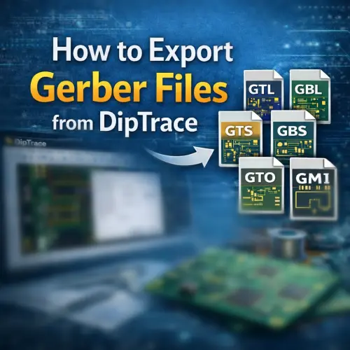
Introduction
DipTrace is a comprehensive EDA/CAD software designed for creating schematic diagrams and printed circuit boards. Known for its intuitive interface, it supports multilingual environments (English plus 21 other languages) and is organized into four logical modules: a schematic-capture editor, a PCB-layout editor with shape-based autorouting and 3D preview/export, a component editor, and a pattern editor.
Compared to complex tools like Altium Designer or Autodesk Eagle, DipTrace offers a more streamlined approach to Gerber generation. However, accuracy is paramount. Before sending your files to manufacturing, we highly recommend validating layers, drill positions, and solder-mask openings using NextPCB's Free Online Gerber Viewer.
Step 1: Initiate Gerber Export
Once your PCB design is finalized and you have performed a Design Rule Check (DRC), you are ready to generate the manufacturing files.
Navigate to the top menu bar and select File > Export > Gerber.
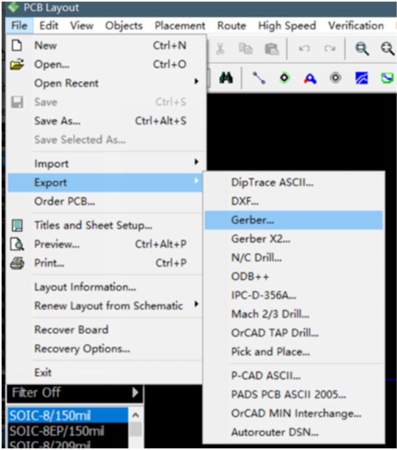
In the Export Gerber window, you will see a list of layers available for export. It is crucial to ensure all necessary layers for board fabrication are selected.
1. Click the "Export All" button. This ensures that all layers defined in your stackup (Top, Bottom, Silk, Mask, Board Outline, etc.) are generated simultaneously.
2. Check your numerical settings. For standard manufacturing with NextPCB, ensure the units match your design (usually Metric or Imperial) and that "Use Apertures" is typically set to Standard.
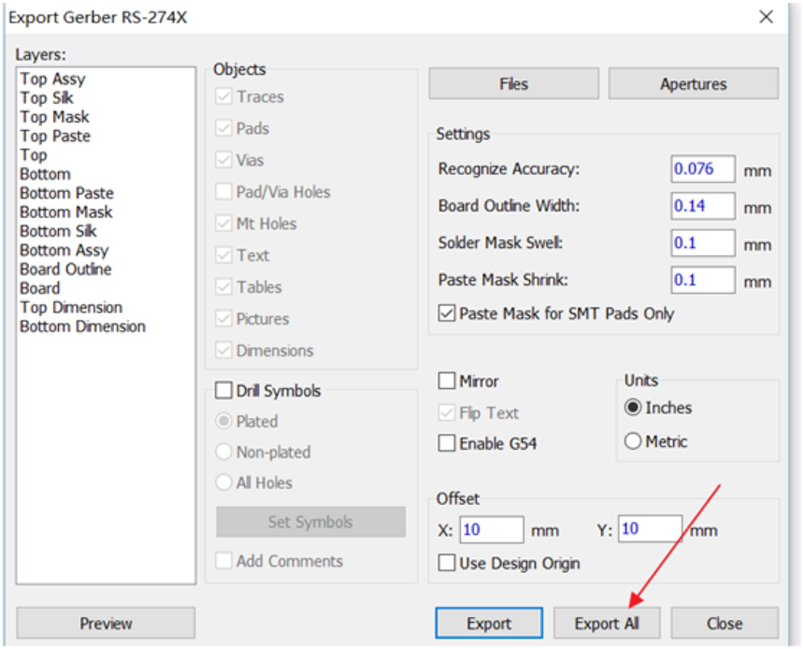
Note: Saving all layers at once is more efficient than exporting them individually, as it reduces the risk of missing a layer.
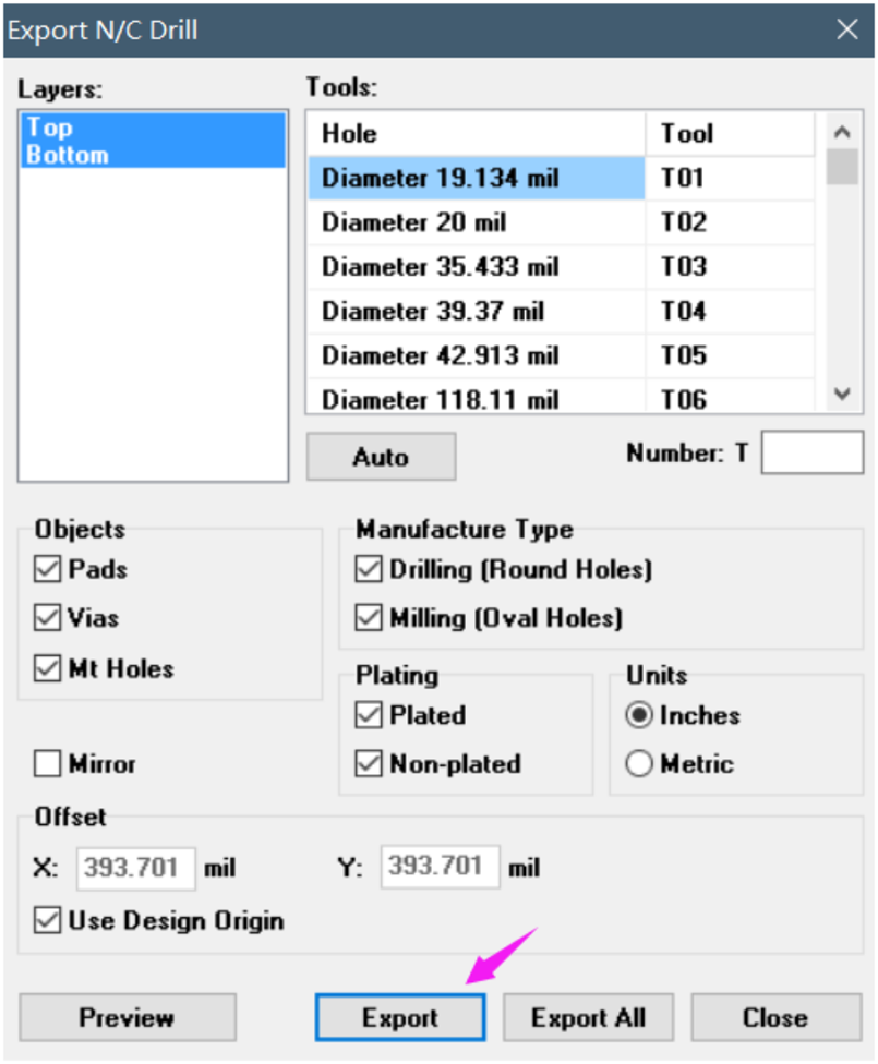
Step 3: Export NC Drill Files
Gerber files define the copper, mask, and silkscreen, but they do not contain drilling information. You must export the N.C. Drill files separately.
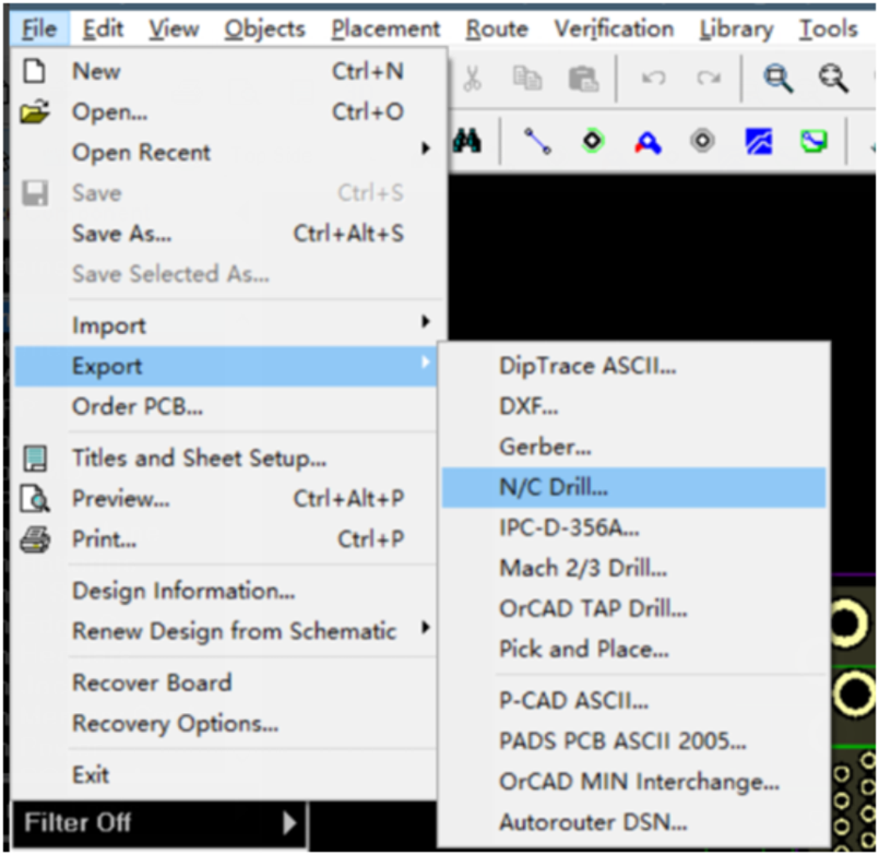
1. Go to File > Export > N.C. Drill.
2. In the dialog box, click the "Auto" button to define the tools based on your design's hole sizes.
3. Click "Export All" to save the drill file (usually with a .drl or .drd extension).
Ensure that the offset coordinates in the Drill export settings match those in the Gerber export settings (usually 0,0) to prevent misalignment between holes and pads.
Next Steps: Manufacturing
You have now successfully exported both the Gerber files and the NC Drill files. These are the standard files required by NextPCB to manufacture your board.
Before uploading, compress all generated files (layers and drills) into a single ZIP file.
Ready to turn your design into reality?
If you encounter any issues with the export process or have specific questions about layer stackups, feel free to contact our engineering support team at support@nextpcb.com.
Get an Instant PCB Quote at NextPCB Engineer Consultation
Frequently Asked Questions (FAQ)
How do I combine Gerber and Drill files in DipTrace?
DipTrace exports Gerber files and Drill files as separate operations. You do not combine them inside the software. Instead, you should export them to the same folder, select all the generated files, and compress them into a single .zip or .rar archive before uploading to the manufacturer.
What are the standard extension names for DipTrace Gerber files?
By default, DipTrace may use extensions like .gbr for all layers or specific extensions like .top (Top Layer), .bot (Bottom Layer), and .drd (Drill). NextPCB accepts standard Gerber RS-274X format regardless of the specific file extension, provided the file content is correct.
Does DipTrace export Pick and Place files?
Yes. If you require PCB Assembly (PCBA) services from NextPCB, you will also need the Pick and Place file. You can generate this by going to File > Export > Pick and Place. Ensure you verify component rotations and reference designators.
Why are my drill holes not aligning with the pads in the Gerber viewer?
This is a common issue caused by coordinate offsets. Ensure that the "Offset" settings (X and Y coordinates) are identical in both the "Export Gerber" dialog and the "Export N.C. Drill" dialog. We recommend keeping both set to (0, 0).

 PCB Assembly
 Layer Buildup
 Online Tools
 PCB Design-Aid & Layout
 Mechanics
 SMD-Stencils
 Quality
 Drills & Throughplating
 Factory & Certificate
 PCB Assembly Factory Show
Certificate
PCB Assembly Factory Show
Certificate
 Printed Circuit Boards
 Surface
 PCB Assembly
 Layer Buildup
 Online Tools
 PCB Design-Aid & Layout
 Mechanics
 SMD-Stencils
 Quality
 Drills & Throughplating
 Factory & Certificate