Introduction
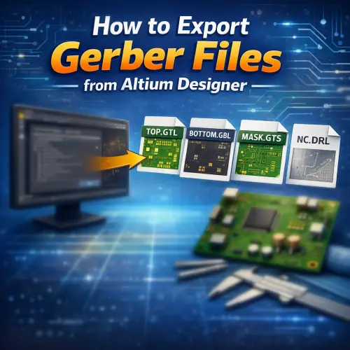
When placing a printed circuit board (PCB) order on the NextPCB website, providing a manufacturing-ready Gerber package is essential for ensuring your design is fabricated correctly. Gerber files are the industry-standard format that translates your digital design into physical instructions for PCB manufacturing equipment.
This article walks you through the process of exporting Gerber files and NC Drill data from Altium Designer step by step.
Pro Tip: After exporting, always preview and validate your layers, drills, solder mask, and silkscreen with NextPCB's Free Online Gerber Viewer before submitting your order to avoid production delays.
- Table of Contents
- Step 1: Open Your PCB Design Files
- Step 2: General Settings Configuration
- Step 3: Layers Setting
- Step 4: Aperture Setting
- Step 5: Advanced Setting
- Step 6: Generating NC Drill Data (Crucial)
- Related Resources
- Frequently Asked Questions (FAQ)
Step 1: Open Your PCB Design Files
Open your .PCBDOC design files in the Altium Designer software.
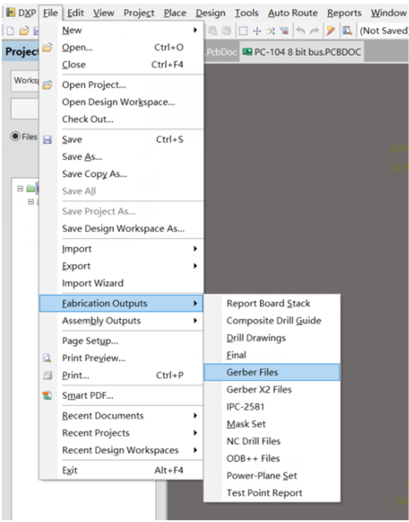
To begin the export process, navigate to the top menu and click: File → Fabrication Outputs → Gerber Files.
Step 2: General Settings Configuration
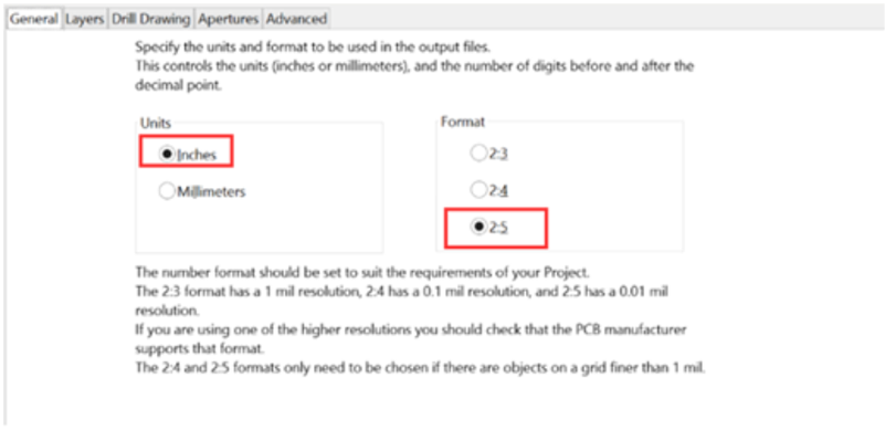
Once the setup window opens, click on the General tab. For professional manufacturing, precision is key.
Please set the format/precision to 2:5 (0.01 mil resolution). This ensures that fine-pitch components and traces are interpreted accurately by the CAM engineers.
Step 3: Layers Setting
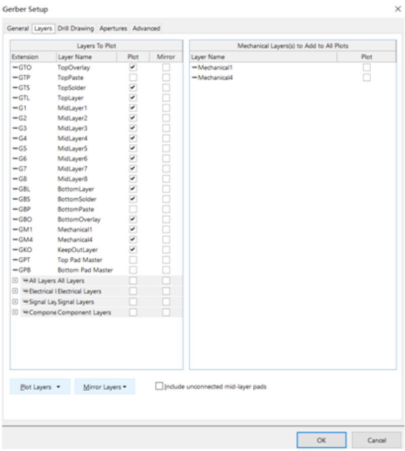
Navigate to the Layers tab. Here you define which physical layers of your board will be exported.
- Outline: Ensure you have a clear, closed outline in the mechanical layer.
- Layer Count: If your board is a 2-layer PCB, there will be no inner layers (G1, G2, etc.) to select.
- Selection: Mark the layers you want to export. To ensure nothing is missed, click "Used On" in the Plot Layers section.
- Mirroring: Ensure "All Off" is selected in the Mirror Layers section (unless you have a specific design reason to mirror them, which is rare for standard fabrication).
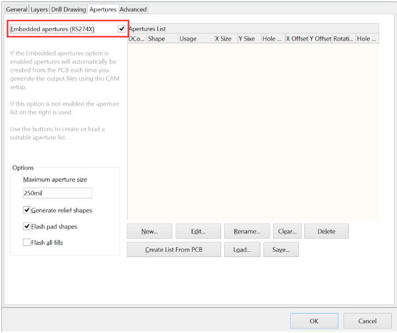
Step 4: Aperture Setting
Go to the Drill Drawing tab (if applicable) and then the Apertures tab.
Make sure to mark the "Embedded apertures (RS-274-X)" format. This is critical because modern CAM software requires the aperture definitions to be embedded within the Gerber file itself, rather than in a separate list.
Step 5: Advanced Setting
In the Advanced tab, verify your film size and position settings.
Once you confirm all configurations are correct (as shown in the reference image below), click OK to generate the Gerber files.
The files will be automatically exported and opened in the Altium CAM viewer. This tool allows you to verify that all layers have been generated correctly and that they are all in positive mode.

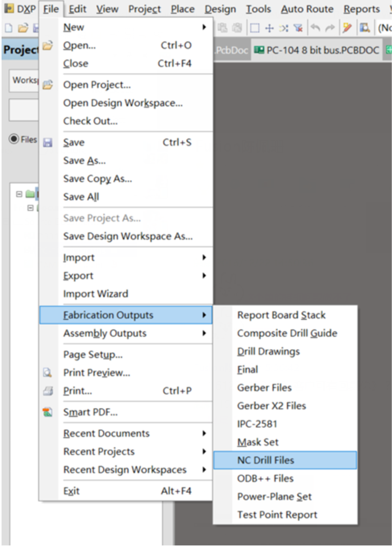
Step 6: Generating NC Drill Data
Generating Gerber files alone is not enough. You must also export the NC Drill data. Many engineers forget this step, resulting in orders being put on hold because the manufacturer does not know where to drill the holes.
A. Access NC Drill Setup
Navigate to: File → Fabrication Outputs → NC Drill Files.
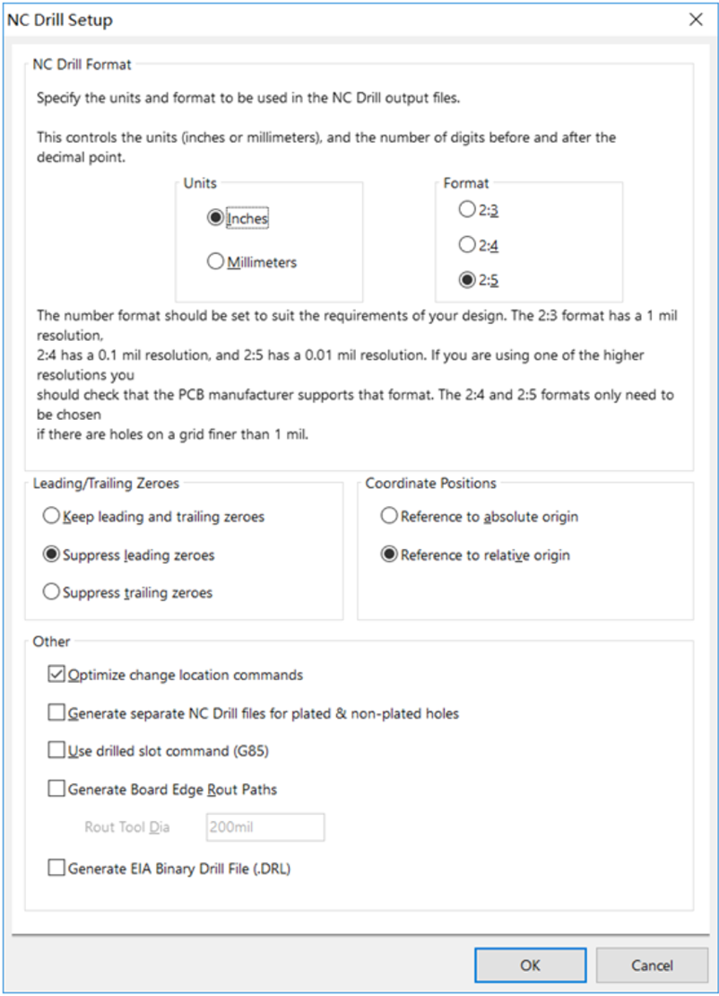
B. Configure Drill Parameters
We recommend choosing the same units and format parameters (e.g., 2:5 resolution, Inches) that you used for the Gerber files in Step 2. This ensures perfect alignment between your copper layers and drilled holes.
Click OK to generate the files.
Finalizing Your Package
After completing these steps, locate the generated files in your project output folder. Zip the Gerber files (typically extensions like .GTL, .GBL, .GTO) together with the NC Drill files (typically .TXT or .DRL).
If you are transitioning between software or want to learn more about PCB file formats, check out these helpful guides:
Frequently Asked Questions (FAQ)
Why do I need to use RS-274-X format?
RS-274-X (Extended Gerber) is the industry standard because it embeds the aperture definitions directly into the file. The older RS-274-D format requires a separate aperture list, which increases the risk of misinterpretation by the manufacturer and production errors.
What is the difference between Gerber files and NC Drill files?
Gerber files define the 2D images of your copper layers, solder mask, and silkscreen. NC Drill files provide the coordinates and tool sizes for the CNC machine to drill holes in the board. Both are required to manufacture a PCB.
Why are my drill holes not showing up in the Gerber Viewer?
If you upload your files to the Online Gerber Viewer and see the copper pads but no holes, you likely forgot to upload the NC Drill file. Ensure you zip the drill file (usually ending in .TXT or .DRL) along with your Gerber layers.
Should I use 2:3, 2:4, or 2:5 format resolution?
For modern PCBs, 2:5 is recommended. This setting offers higher precision (up to 0.00001 inch), which is necessary for complex designs with tight tolerances. Lower resolutions like 2:3 may result in rounding errors.
If you have any questions about your file generation, feel free to contact our engineering support at support@nextpcb.com.

 PCB Assembly
 Layer Buildup
 Online Tools
 PCB Design-Aid & Layout
 Mechanics
 SMD-Stencils
 Quality
 Drills & Throughplating
 Factory & Certificate
 PCB Assembly Factory Show
Certificate
PCB Assembly Factory Show
Certificate
 Printed Circuit Boards
 Surface
 PCB Assembly
 Layer Buildup
 Online Tools
 PCB Design-Aid & Layout
 Mechanics
 SMD-Stencils
 Quality
 Drills & Throughplating
 Factory & Certificate