Table of Contents
- What is Eagle Software?
- The PCB Layout Editor
- Step 1: Open the CAM Processor
- Step 2: Load the CAM Job
- Step 3: Select the Gerber Standard
- Step 4: Adding a Second Silkscreen (Optional)
- Step 5: Process the Job
- Step 6: Generating Your Drill File
- Frequently Asked Questions (FAQ)
What is Eagle Software?
EAGLE is a scriptable electronic design automation (EDA) application featuring schematic capture, printed circuit board (PCB) layout, auto-router, and computer-aided manufacturing (CAM) capabilities. EAGLE stands for Easily Applicable Graphical Layout Editor (German: Einfach Anzuwendender Grafischer Layout-Editor). Originally developed by CadSoft Computer GmbH, the software was acquired by Autodesk Inc. in 2016.
EAGLE contains a schematic editor for designing circuit diagrams. Schematics are stored in files with the .SCH extension, while parts are defined in device libraries with the .LBR extension. Parts can be placed on multiple sheets and connected together through ports.
The PCB Layout Editor
The PCB layout editor stores board files with the .BRD extension. It enables back-annotation to the schematic and allows the auto-router to automatically connect traces based on the connectivity defined in the schematic design.
When you finish your PCB design in Eagle, you must generate Gerber files required by PCB manufacturers. This guide outlines the precise steps to export standard Gerber files from Eagle software.
Already Have Demo Files?
Try HQDFM Free Online Gerber Viewer Now!
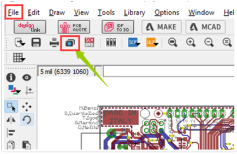
Step 1: Open the CAM Processor
Open your PCB layout (.brd) file in Eagle. Click the "CAM" button or navigate to the menu and choose File -> CAM Processor. This will launch the CAM Processor tool used to generate the manufacturing files.
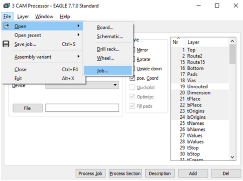
Step 2: Click File -> Open -> Job
In the CAM Processor window, you need to load a predefined job configuration to ensure the correct layers are exported.
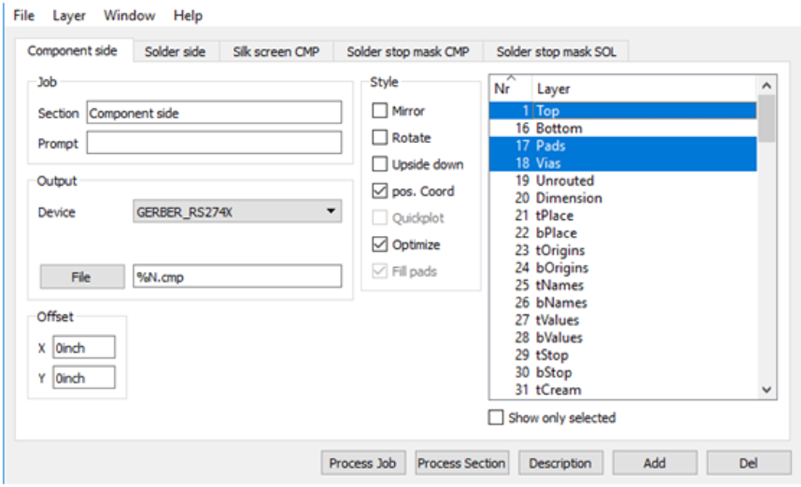
Step 3: Select the Gerber Standard
Navigate to your default EAGLE CAM folder. Choose the GERBER_RS274x.cam file (standard RS-274X format) and press Open.
Step 4: Adding a Second Silkscreen (Optional)
By default, the standard job might not include a configuration for the bottom silkscreen. If your design requires a silkscreen on the bottom layer, follow these configuration steps:
- Click Add within the CAM processor.
- Change the Section name to something descriptive, like "Silk Screen SOL".
- Change the output File extension to "%N.pls".
- Deselect all currently selected layers.
- Select the specific bottom layers required:
- Layer 20: Dimension
- Layer 22: bPlace (Bottom Placement)
- Layer 26: bNames (Bottom Names)
Step 5: Process the Job
Select the Process Job button to create all of your Gerber files. Once completed, you can find all generated Gerber files in your project folder via the Autodesk EAGLE Control Panel.
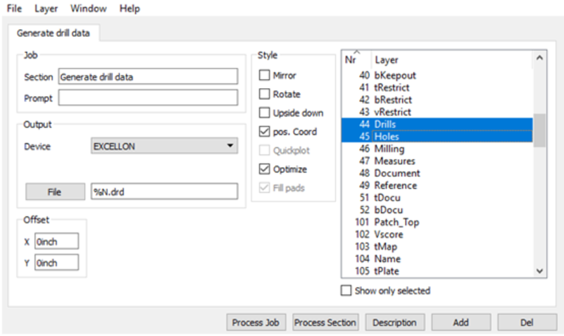
Step 6: Generating Your Drill File
Gerber files define the copper and silkscreen, but you also need an Excellon file for drilling holes.
- Select the CAM Processor at the top of your interface or select File » CAM Processor to reopen the dialog (if closed).
- Load the drill configuration job: Select File » Open » Job.
- Navigate to your default EAGLE CAM folder and select the excellon.cam file, then select Open.
- You will now see a single "Generate drill data" tab. This job captures data from Layer 44 (Drills) and Layer 45 (Holes).
- Select the Process Job button to generate the drill file.
After completing these steps, both the Gerber files and Drill data have been successfully exported from Eagle software and are ready for manufacturing.
Frequently Asked Questions (FAQ)
1. Why is RS-274X preferred over older Gerber formats?
RS-274X (Extended Gerber) is the industry standard because it embeds aperture definitions (shape and size of pads) directly into the file. Older formats like RS-274D require a separate aperture file, which can lead to version mismatches and manufacturing errors.
2. How can I verify that my Gerber files are correct?
Before sending your files to a manufacturer, you should always check them visually. You can use the HQDFM Free Online Gerber Viewer to inspect your layers and ensure the drill holes align with the pads.
3. My CAM Processor looks different, why?
Autodesk Eagle has updated its interface in newer versions (specifically Eagle 9 and later). While the general logic remains the same (selecting layers and exporting), the UI might differ. This guide focuses on the classic workflow which is robust for many versions.
Start Your PCB Fabrication
Now that you have your production files ready, ensure your design is brought to life with high precision and reliability.
Get an Instant Quote for Your PCB Assembly and Manufacturing at NextPCB
If you have further questions regarding PCB fabrication, feel free to contact support@nextpcb.com.

 PCB Assembly
 Layer Buildup
 Online Tools
 PCB Design-Aid & Layout
 Mechanics
 SMD-Stencils
 Quality
 Drills & Throughplating
 Factory & Certificate
 PCB Assembly Factory Show
Certificate
PCB Assembly Factory Show
Certificate
 Printed Circuit Boards
 Surface
 PCB Assembly
 Layer Buildup
 Online Tools
 PCB Design-Aid & Layout
 Mechanics
 SMD-Stencils
 Quality
 Drills & Throughplating
 Factory & Certificate