PCB Assembly
Stacy Lu

 NextPCB Capabilities
Printed Circuit Boards
 Process Capabilities
 PCB Design-Aid & Layout
 Quality
 Drills & Throughplating
 Factory & Certificate
 PCB Assembly Factory Show
Certificate

Support Team
Feedback:
support@nextpcb.com


An optocoupler, also called an opto isolator, passes a signal between two circuits using light, so the circuits stay electrically isolated. Inside the package, an LED on the input side faces a light sensor on the output side. The sensor is usually a phototransistor. When current flows through the LED, it emits light, the sensor conducts, and the output switches. No electrical connection crosses the gap.
This guide explains how an optocoupler works, how to read its symbol and pinout, the main types, the specs to check, a worked circuit example, and PCB layout tips.
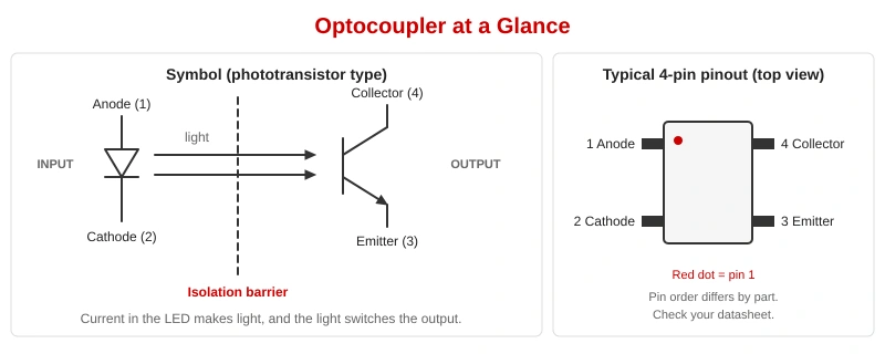
An optocoupler is a component that transfers a signal with light across an isolation barrier. It is used when two circuits must share a signal but must not share a ground or a direct electrical path, for example a low-voltage microcontroller and a higher-voltage circuit.
The names optocoupler, opto isolator, optoisolator and photocoupler mean the same thing. This guide uses "optocoupler".
Because only light crosses the gap, high voltage spikes and ground noise on one side do not travel to the other side, up to the isolation rating of the part.
The optocoupler symbol shows an LED on one side and a light sensor on the other, separated by a dashed line or a gap. The LED uses the normal diode triangle and bar, with arrows pointing toward the sensor. See our diode symbols guide for how to read the LED symbol. On the output side, a phototransistor looks like a transistor with arrows pointing in, and our transistor symbols guide explains the collector and emitter pins.
Many common 4-pin optocouplers use this pin order. Six-pin parts add a base pin. Always confirm the pinout in the datasheet of your exact part.
| Pin | 4-pin optocoupler | 6-pin optocoupler (with base) |
|---|---|---|
| 1 | Anode (LED +) | Anode (LED +) |
| 2 | Cathode (LED -) | Cathode (LED -) |
| 3 | Emitter | Not connected on many parts |
| 4 | Collector | Emitter |
| 5 | - | Collector |
| 6 | - | Base |
| Type | Output side | Typical use |
|---|---|---|
| Phototransistor | Phototransistor | General signal isolation, such as microcontroller inputs and outputs |
| Photodarlington | Two transistors in a Darlington pair | Higher gain from a small LED current, but slower |
| Photo-triac | Triac driver | Switching AC loads from a low-voltage control circuit |
| Logic-gate (high-speed) | Photodiode with a logic gate | Fast digital communication lines |
| Linear | Photodiode pair | Isolating analog signals or feedback in a power supply |
| Spec | What it means |
|---|---|
| Current transfer ratio (CTR) | Output current divided by LED input current, shown as a percentage. For example, a CTR of 50% at 10 mA of LED current gives up to 5 mA of output current. CTR changes with LED current, temperature and age. |
| Forward current and voltage of the LED | The current the LED needs and the voltage across it. You need these to size the input resistor. |
| Isolation voltage | The voltage the barrier is rated to withstand between input and output. The datasheet states the test conditions. |
| Collector-emitter voltage | The maximum voltage the output transistor can take. |
| Switching speed | Rise and fall time. Phototransistor types are slower than logic-gate types. |
| Operating temperature | The temperature range for which the ratings apply. |
This example isolates a 5 V logic signal from a microcontroller that runs on 3.3 V. The values are examples, so check the datasheet of your part.
The input side is a normal LED circuit. Use this formula: R = (Vin - Vf) / If. With Vin = 5 V, an LED forward voltage Vf of about 1.2 V and a forward current If of 10 mA, R = (5 - 1.2) / 0.01 = 380 ohms. The nearest standard value is 390 ohms, which gives about 9.7 mA. For more on sizing, see our LED resistor guide.
Connect the emitter to the microcontroller ground and the collector to a 3.3 V pull-up resistor of 10 kilohms. The collector is also the signal line to the microcontroller input.
With the LED on, the output transistor can pass up to CTR x If. At a CTR of 50% and 9.7 mA, that is up to about 4.8 mA. The pull-up only needs about 0.3 mA (3.3 V / 10 kilohms), so the transistor saturates and pulls the collector low. With the LED off, the pull-up holds the collector high.
| Part | Example value | Role |
|---|---|---|
| LED resistor | 390 ohms | Sets the LED current to about 9.7 mA |
| Pull-up resistor | 10 kilohms | Holds the output high when the LED is off |
| Output logic | Inverted | Output is low when the LED is on |
Note that the output is inverted: the signal is low when the input is on. Invert it in software, or add a second stage if you need the same polarity. A larger pull-up saves current but slows the switching.
For other symbols you will meet on a schematic, see our PCB schematic symbols visual reference and electronic component symbols guides.
An optocoupler passes a signal between two circuits while keeping them electrically isolated. It protects low-voltage logic from high voltage, noise and ground differences.
Yes. Optocoupler, opto isolator, optoisolator and photocoupler are different names for the same type of component.
CTR is the current transfer ratio. It is the output current divided by the LED input current, shown as a percentage.
Use R = (Vin - Vf) / If. Take Vf and If from the datasheet. For example, 5 V, 1.2 V and 10 mA give 380 ohms, so use 390 ohms.
Test the input side like a diode: in diode mode on a multimeter, the LED shows a forward voltage drop in one direction. For the output side, power the LED through a resistor and check that the output transistor conducts. Make sure you do not exceed the LED current rating.
Standard phototransistor types are not linear enough for analog signals. Linear optocouplers are made for that job.
An optocoupler isolates two circuits with light. Size the LED resistor from the datasheet values, check CTR and the isolation rating, keep the gap clear on the PCB, and confirm the pinout before you finish the footprint.

Still, need help? Contact Us: support@nextpcb.com
Need a PCB or PCBA quote? Quote now