
 NextPCB Capabilities
Printed Circuit Boards
NextPCB Capabilities
Printed Circuit Boards
 PCB Assembly
 Layer Buildup
 SMD-Stencils
 PCB Design-Aid & Layout
 Mechanics
 Quality
 Drills & Throughplating
 Factory & Certificate
 PCB Assembly Factory Show
Certificate
PCB Assembly Factory Show
Certificate
Support Team
Feedback:
support@nextpcb.com


An LED requires a series current-limiting resistor calculated as R = (Vs − Vf) / If . Without this resistor, the LED draws uncontrolled current and fails within seconds due to thermal runaway.
LED Resistor Formula: R = (Vs − Vf) / If
Example — 5V supply, Red LED, 20mA:
R = (5.0 − 2.0) / 0.020 = 150Ω
Example — 5V supply, Blue LED, 20mA:
R = (5.0 − 3.3) / 0.020 = 85Ω → use 82Ω or 100Ω
R = (Vs − Vf) / If
| Variable | Description | Unit |
|---|---|---|
| R | Series resistance | Ω |
| Vs | Supply voltage | V |
| Vf | LED forward voltage | V |
| If | Desired forward current | A (divide mA by 1000) |
Given: 5V supply · Red LED (Vf = 2.0V) · Target current 20mA
Voltage across resistor: 5.0 − 2.0 = 3.0V
Resistance: 3.0V ÷ 0.020A = 150Ω
Nearest E24 standard value: 150Ω (exact) or 180Ω for a safety margin
Resistor power: P = If2 × R = (0.020)2 × 150 = 0.06W → use 0.25W rated part
| Supply | LED Color | Vf (typ.) | Target If | Resistor |
|---|---|---|---|---|
| 5V | Red / Orange | 2.0V | 20mA | 150–180Ω |
| 5V | Yellow / Green (std) | 2.1V | 20mA | 150Ω |
| 5V | Blue / White | 3.3V | 20mA | 82–100Ω |
| 5V | Green (high-brightness) | 3.2V | 20mA | 82–100Ω |
| 3.3V | Red | 2.0V | 10mA | 120–150Ω |
| 3.3V | Blue / White | 3.3V | 5mA | 0–22Ω* |
| 12V | Red | 2.0V | 20mA | 470–510Ω |
| 12V | Blue / White | 3.3V | 20mA | 430–470Ω |
*At 3.3V with a blue/white LED (Vf ≈ 3.3V), voltage headroom is near zero. Limit to 5mA or less. A 22Ω resistor provides minimum protection.
Key takeaway: For most 5V indicator circuits, 150–220Ω is a safe working range for red/orange/yellow LEDs. Always round up to the next standard resistor value to stay within current limits.
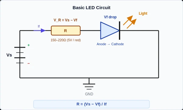
The basic LED circuit places a current-limiting resistor in series between the supply voltage and the LED anode. Complete current path:
Vs (+) → [R] → LED anode → LED cathode → GND
An LED is not a resistive device. Its current increases exponentially with voltage above Vf — a 0.1V increase above threshold can multiply current several times over. Without a resistor, the supply drives far more current than the junction can handle. Temperature rises, Vf drops, current increases further: thermal runaway. The LED fails in under one second.
The resistor absorbs the voltage difference (Vs − Vf) and enforces a safe operating current regardless of supply impedance.
Direct to 5V supply: Several hundred milliamps through a 2V red LED. Junction destroyed within one second.
Direct to 1.5V AA battery: Still enough above Vf to cause damage in many LEDs — even a battery has enough current delivery to overdrive a junction.
After failure: The LED either goes dark immediately or operates at a fraction of rated brightness before dying from bond wire fatigue.
Key takeaway: Never connect an LED directly to any supply voltage — even low-voltage sources. The resistor is not optional.
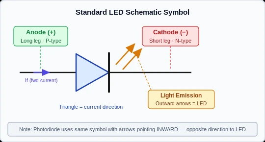
| Element | Location | Meaning |
|---|---|---|
| Filled triangle | Left | Anode (+), P-type semiconductor |
| Vertical bar | Right of triangle tip | Cathode (−), N-type semiconductor |
| Two diagonal arrows | Projecting outward | Light emission (photon output) |
Current flows from anode (triangle base) → cathode (bar). The outward arrows are the sole visual distinction between an LED and a standard rectifier diode, which uses identical triangle-bar geometry.
LED vs. Photodiode: A photodiode uses arrows pointing inward (toward the junction), indicating light absorption. Always confirm arrow direction in mixed-diode schematics.
Reversed polarity does not always cause visible damage immediately. At 3.3V with a reverse breakdown voltage of 5–6V, a reversed LED simply does not light — it may survive indefinitely. At 5V or higher, sustained reverse bias risks breakdown and permanent failure. Verify polarity with a multimeter in diode-test mode before powering the circuit.
Key takeaway: Long leg = anode = (+). Flat side on lens = cathode = (−). On PCB, "K" or flat silkscreen edge = cathode.
Vf is determined by semiconductor material, not by LED physical size or brightness rating. Values below are at 20mA, 25°C junction temperature.
| LED Color | Material | Vf Typical (V) | Vf Range (V) | Max If (mA) |
|---|---|---|---|---|
| Infrared (IR) | GaAs / AlGaAs | 1.2 | 1.0 – 1.6 | 100 |
| Red | AlGaAs / GaAsP | 1.8 | 1.6 – 2.2 | 30 |
| Orange | GaAsP | 2.0 | 1.8 – 2.3 | 30 |
| Yellow | GaAsP / AlGaInP | 2.1 | 1.8 – 2.4 | 30 |
| Green (standard) | GaP | 2.1 | 1.9 – 2.4 | 25 |
| Green (high-brightness) | InGaN | 3.2 | 2.9 – 3.6 | 30 |
| Blue | InGaN | 3.3 | 3.0 – 3.6 | 30 |
| White | InGaN + phosphor | 3.3 | 3.0 – 3.6 | 30 |
| UV | InGaN | 3.5 | 3.2 – 4.0 | 20 |
Engineering note: Vf decreases approximately −2mV per °C as junction temperature rises. Design your resistor using the minimum Vf in the datasheet range — this is the highest-current worst case. At 85°C, a red LED's Vf may drop from 2.0V to 1.8V, increasing current by ~15% through a fixed resistor.
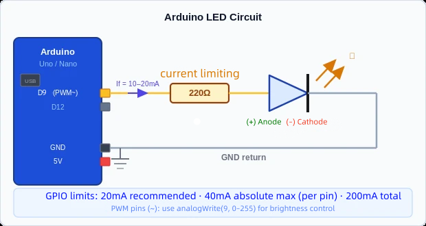
Arduino Pin D13 → [220Ω] → LED (+) → LED (−) → GND
Arduino digital output pins are rated at 40mA absolute maximum, with 20mA recommended per pin and 200mA total across all I/O on AVR-based boards (Uno, Nano, Mega). Running at 10mA is standard practice for indicator LEDs — it extends GPIO life and reduces total power draw.
| Board Voltage | LED Color | Vf | If Target | Resistor |
|---|---|---|---|---|
| 5V (Uno, Mega) | Red | 2.0V | 10mA | 330Ω |
| 5V (Uno, Mega) | Blue / White | 3.3V | 10mA | 180Ω |
| 3.3V (Nano 33, MKR) | Red | 2.0V | 5mA | 270Ω |
| 3.3V (Nano 33, MKR) | Blue / White | 3.3V | 5mA | 0–22Ω |
const int LED_PIN = 13;

void setup() {
  pinMode(LED_PIN, OUTPUT);
}

void loop() {
  digitalWrite(LED_PIN, HIGH);  // LED on
  delay(1000);
  digitalWrite(LED_PIN, LOW);   // LED off
  delay(1000);
}
Pins marked ~ on Arduino boards (3, 5, 6, 9, 10, 11 on Uno) support analogWrite(pin, 0–255) . PWM frequency is approximately 490Hz on most pins. For camera-facing indicators or high-flicker-sensitivity environments, use an external PWM controller operating at 20kHz+ to eliminate visible artifacts.
For detailed pin mapping and PWM assignments across Arduino form factors, including PCB layout considerations, see the Arduino Nano pinout diagram and PCB design guide.
Key takeaway: Use 330Ω for a 5V red LED at 10mA on Arduino GPIO. Never exceed 20mA per pin in any sustained condition.
Engineering note: Always design for the lowest expected Vf to ensure the resistor holds current in range across the full operating temperature. This single constraint prevents most LED circuit failures in production.
For production boards transitioning from prototype, manufacturing quality directly affects LED circuit reliability. NextPCB provides PCBA services with 24-hour lead time, IPC standard manufacturing, and full BOM sourcing support — covering component procurement, reflow, and post-assembly AOI inspection in a unified workflow.
What resistor do I use for a 5V LED?
For red/orange (Vf ≈ 2.0V) at 20mA: 150Ω. For blue/white (Vf ≈ 3.3V) at 20mA: 82–100Ω. When LED color is unknown, 220Ω is a conservative safe default for any 5V indicator circuit.
Can I connect an LED without a resistor?
No. Without a current-limiting resistor, an LED will draw uncontrolled current from any low-impedance supply and fail in under a second. The only exception: some dedicated LED driver ICs incorporate internal current limiting.
Why does my LED burn out immediately?
Four most common causes: (1) no series resistor, (2) resistor value too low, (3) reversed polarity at voltages above 6V, (4) supply voltage exceeds LED's maximum rating. Check these in order before replacing the component.
How do I identify which LED leg is positive?
Longer lead = anode (+). Flat edge on the lens base = cathode (−). On SMD: check datasheet marking or use a multimeter in diode-test mode — forward bias lights the LED with the probe polarity matching anode/cathode.
Can I connect multiple LEDs in parallel?
Yes, but only with individual series resistors for each LED. Shared resistors cause uneven current due to Vf mismatch within the batch.
What is PWM dimming and does it affect the resistor?
PWM switches the LED on/off rapidly (490Hz–20kHz+) to control apparent brightness. The resistor calculation still applies to the fully-on state — the duty cycle does not change the peak current or the resistor value required.
| Parameter | Value | Notes |
|---|---|---|
| Red LED Vf | 1.6 – 2.2V | Typical 1.8V at 20mA, 25°C |
| Blue / White LED Vf | 3.0 – 3.6V | InGaN junction |
| Standard indicator current | 10 – 20mA | Most through-hole indicator LEDs |
| Resistor for 5V / red LED | 150 – 220Ω | At 10–20mA; use 220Ω for margin |
| Resistor for 5V / blue LED | 82 – 100Ω | At 20mA |
| Vf temperature coefficient | −2mV / °C | Current increases with temperature |
| Arduino GPIO max (AVR) | 40mA abs. / 20mA recommended | 200mA total I/O budget |
| LED reverse breakdown voltage | 5 – 6V | Standard indicator grade |
Still, need help? Contact Us: support@nextpcb.com
Need a PCB or PCBA quote? Quote now


 Surface

