PCB Assembly

Lolly Zheng- Sales Account Manager at NextPCB.com

 NextPCB Capabilities
Printed Circuit Boards
 Process Capabilities
 PCB Design-Aid & Layout
 Quality
 Drills & Throughplating
 Factory & Certificate
 PCB Assembly Factory Show
Certificate

Support Team
Feedback:
support@nextpcb.com


A Zener diode is a diode designed to conduct in reverse once the voltage across it reaches a specific, stable value called the Zener voltage (Vz). Below that voltage it blocks current like a normal reverse-biased diode. At and above it, the diode conducts while holding its voltage almost constant. That behavior makes it a simple, low-cost way to create a reference voltage, regulate a small load or clamp a signal.
This guide covers what a Zener diode does, how to read its symbol, how it works, the specifications that matter, a voltage regulator circuit with a worked calculation, how to test one, and what to watch for when you place it on a PCB.
A Zener diode is a two-terminal semiconductor device built to operate safely in the reverse breakdown region. A regular rectifier diode can be damaged when pushed into breakdown. A Zener diode is doped so that its breakdown voltage is well defined and repeatable, and it is packaged to dissipate the resulting power.
In practice, a Zener diode does three jobs:
| Quick facts | Detail |
|---|---|
| Normal operating mode | Reverse biased, in breakdown |
| Typical voltage values | 2.4 V to 200 V, with common values such as 3.3 V, 5.1 V, 9.1 V, 12 V and 24 V |
| Always needed in the circuit | A series resistor that limits current |
| Common uses | Reference voltage, small shunt regulator, clamp, gate protection |
The Zener diode symbol looks like a standard diode symbol, a triangle pointing at a bar, but the cathode bar has its two ends bent into a "Z" shape. The triangle points from the anode (A) to the cathode (K), which is the direction of normal forward current. In a regulator, the cathode connects toward the more positive side, because the diode is used in reverse.
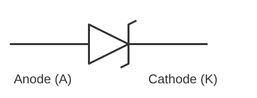
Symbol variations exist between standards and drawing tools, but the bent cathode bar is the part to look for. If you need a broader reference, see our guide to electrical and electronic symbols and the PCB schematic symbols visual reference.
| Diode type | How the symbol differs | Used for |
|---|---|---|
| Standard diode | Triangle and straight bar | Rectification, reverse protection |
| Zener diode | Bar ends bent in a "Z" shape | Reference and regulation in reverse breakdown |
| Schottky diode | Bar ends bent in an "S" shape | Low forward drop, fast switching |
| TVS diode | Often drawn like a Zener; bidirectional parts show two triangles | Surge and ESD protection |
A Zener diode has two operating regions that matter:
That flat part of the reverse curve is what makes the device useful. If the current through the diode changes, the voltage across it stays close to Vz. The resistor in series with it takes up the difference between the input voltage and Vz.
Two physical effects cause the breakdown. The Zener effect dominates in low-voltage parts, roughly below 5 V. Avalanche breakdown dominates above about 6 V. Between them, around 5 V to 6 V, the two effects offset each other and the temperature drift of the voltage is smallest, which is why 5.1 V and 5.6 V parts are popular where stability matters.
Read these values on the datasheet before choosing a part.
| Parameter | What it means | Why it matters |
|---|---|---|
| Zener voltage (Vz) | Voltage across the diode at a stated test current | Sets the regulated or clamped voltage |
| Tolerance | Allowed spread of Vz, commonly ±5%, with tighter grades available | Decides how accurate a reference you get |
| Power rating (Pd) | Maximum continuous power the package can dissipate | Sets maximum current: Iz(max) = Pd / Vz |
| Dynamic impedance (Zz) | How much Vz changes as current changes | Lower is better for regulation |
| Knee current (Izk) | Minimum current to stay in stable breakdown | Below it, regulation gets poor |
| Temperature coefficient | Drift of Vz with temperature | Important for references; near zero around 5 V to 6 V |
Power ratings depend on the package. For example, the 1N47xx series comes in a DO-41 package rated about 1 W, and the BZX84 series in a SOT-23 package is in the 250 mW class. Always confirm values against the manufacturer's datasheet.
The basic Zener diode as a voltage regulator is a shunt regulator. A series resistor (Rs) connects the input to the Zener diode, the diode connects to ground with its cathode toward the input, and the load connects in parallel with the diode.
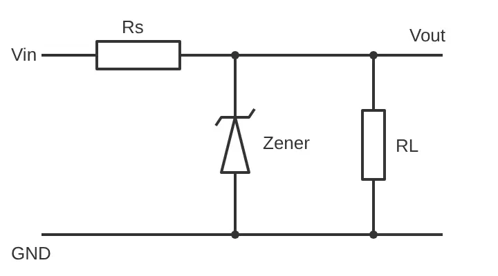
The diode holds the output near Vz. The current through Rs equals the load current plus the Zener current. When the load draws less, the Zener takes more of that current, and the other way around, so the output voltage stays nearly fixed.
| Step | Calculation | Result |
|---|---|---|
| Given | Vz = 5.1 V, IL(max) = 20 mA, Iz(min) = 5 mA, Vin = 9 V to 15 V | — |
| Maximum Rs | (9 − 5.1) / (0.020 + 0.005) = 3.9 / 0.025 | 156 Ω |
| Chosen Rs | Next standard value below 156 Ω | 150 Ω |
| Worst-case current at 15 V, no load | (15 − 5.1) / 150 = 9.9 / 150 | 66 mA |
| Zener power | 5.1 V × 0.066 A | 0.34 W → use a 1 W part |
| Resistor power | 9.9² / 150 | 0.65 W → use a 1 W resistor |
This example shows the main limit of a Zener regulator: it wastes power continuously and the output moves with the load. For higher currents or tighter regulation, add a transistor stage after the Zener or use a dedicated linear or switching regulator.
The question "what is the difference between a diode and a Zener diode" comes down to the region each one is designed for.
| Type | Designed to work in | Strength | Limit |
|---|---|---|---|
| Rectifier diode | Forward conduction, blocks reverse | Converts AC to DC | Breakdown is not controlled and can damage it |
| Zener diode | Reverse breakdown at a set voltage | Stable voltage reference and clamp | Limited power, needs a series resistor |
| Schottky diode | Forward conduction with low drop | Low loss, fast switching | Higher reverse leakage, low reverse voltage ratings |
| TVS diode | Fast clamping of short surges | Handles high pulse energy | Not meant for continuous regulation |
A Zener diode and a TVS diode look alike on paper, but a Zener is meant for steady regulation while a TVS is built to absorb brief, high-energy surges. For surge protection design, read our guide to TVS diode PCB design and the comparison of varistor (MOV) vs TVS diode. For the standard rectifying type, see rectifier diode working and applications.
Ready to build your board? You can get a PCB quote with NextPCB.
A Zener diode keeps the voltage across it nearly constant when it is reverse biased past its breakdown voltage. It is used as a voltage reference, a small shunt regulator and a voltage clamp.
Zener voltage (Vz) is the reverse voltage at which the diode begins to conduct strongly and hold its voltage. It is specified at a test current on the datasheet.
Connect it in reverse: the cathode toward the positive supply and the anode toward ground, with a series resistor on the supply side to limit current. The load goes in parallel with the diode.
Once in breakdown, the diode's resistance is low, so current is limited only by the external circuit. Without a series resistor, the current rises until the diode overheats.
Not for regulation. A regular diode is not specified for a defined breakdown voltage and can be damaged in reverse breakdown. In forward direction, you can stack regular diodes to get roughly 0.7 V per diode as a rough reference.
Both operate in reverse breakdown. The Zener effect dominates below roughly 5 V, avalanche breakdown dominates above roughly 6 V. Many parts called Zener diodes above 6 V actually rely on avalanche breakdown.
A Zener diode is one of the simplest ways to set a voltage reference or protect a node: reverse bias it, limit the current with a resistor, and size both for the worst case. Pick the voltage and power rating from the datasheet, mark the cathode correctly on the PCB, and check the regulated voltage on the finished board.

Still, need help? Contact Us: support@nextpcb.com
Need a PCB or PCBA quote? Quote now