PCB Assembly
Arya Li, Project Manager at NextPCB.com

 NextPCB Capabilities
Printed Circuit Boards
 Process Capabilities
 PCB Design-Aid & Layout
 Quality
 Drills & Throughplating
 Factory & Certificate
 PCB Assembly Factory Show
Certificate

Support Team
Feedback:
support@nextpcb.com


A diode symbol is a triangle pointing at a vertical bar. The triangle is the anode and the bar is the cathode, and the triangle points in the direction of conventional current flow. Small changes to the bar or extra arrows tell you which type of diode it is: a Zener diode has a bent bar, a Schottky diode has a hooked bar, an LED has arrows pointing away, and a photodiode has arrows pointing in.
This guide shows every common diode symbol in one chart, explains how to tell them apart, how to find the cathode on the schematic and on the PCB, and which reference designators to expect.
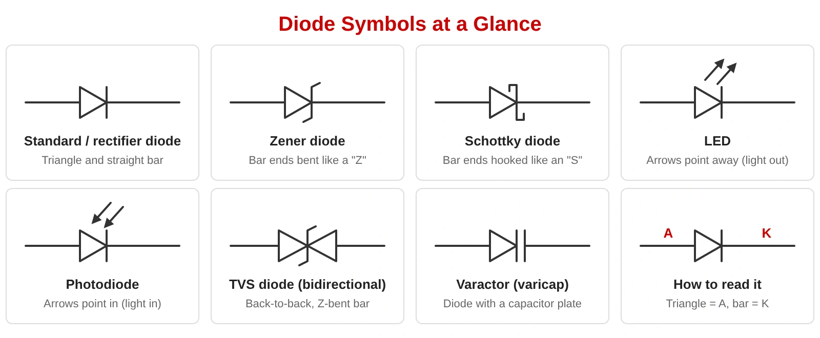
| Diode type | How the symbol differs | Typical designator | Main use |
|---|---|---|---|
| Standard or rectifier diode | Triangle and straight bar | D | Rectification, reverse-polarity protection, signal steering |
| Zener diode | Bar ends bent in a "Z" shape | ZD, DZ or D | Voltage reference and clamping |
| Schottky diode | Bar ends hooked in an "S" shape | D | Low-loss rectification and fast switching |
| LED | Diode with two arrows pointing away | D or LED | Indicators and lighting |
| Photodiode | Diode with two arrows pointing toward it | D or PD | Light sensing |
| TVS diode | Zener-style bar; bidirectional parts show two diodes back to back | D or TVS | Surge and ESD protection |
| Varactor (varicap) | Diode with a capacitor plate next to the bar | D or VD | Voltage-controlled capacitance |
Designators vary between companies and EDA libraries, so follow your own library or the standard your customer specifies.
In the basic symbol, current flows easily from the anode (triangle side) to the cathode (bar side) when the diode is forward biased. In the opposite direction the diode blocks current. Think of the triangle as an arrow and the bar as a wall the arrow points at.
The same symbol is used for general-purpose signal diodes and for the rectifier diode used in power supplies. The part number, not the symbol, tells you the current and voltage ratings. For more symbols beyond diodes, see the PCB schematic symbols visual reference and our guide to electrical and electronic circuit symbols.
The Zener symbol bends both ends of the cathode bar into a "Z" shape. Zener diodes are normally used reverse biased, so on a schematic the cathode usually faces the more positive rail. Read more in our guide to the Zener diode, including its working principle and regulator circuit.
The Schottky symbol hooks the ends of the cathode bar into an "S" shape. Schottky diodes have a low forward voltage drop, typically about 0.2 V to 0.4 V, and switch quickly, which is why they appear in switching converters and low-voltage rectifiers.
The two symbols are easy to mix up because both change the shape of the cathode bar. The difference is in the shape of the bent ends:
| Feature | Zener diode | Schottky diode |
|---|---|---|
| Bar ends | Slanted, forming a "Z" | Square hooks, forming an "S" |
| Normal operation | Reverse biased, in breakdown | Forward biased, low drop |
| Used for | Voltage reference, clamping | Efficient rectification, fast switching |
An LED is drawn as a diode with two arrows pointing away from it, showing emitted light. The anode connects to the positive side through a current-limiting resistor. See our guide to the LED resistor calculation, circuit diagram and symbol guide for sizing the resistor.
A photodiode is drawn like an LED, but the two arrows point toward the diode to show incoming light. It is usually used reverse biased, or at zero bias, to turn light into current in sensors and optical receivers. For a wider view of device families, see semiconductor device types.
A unidirectional TVS diode looks like a Zener symbol. A bidirectional TVS shows two diodes back to back, and protects against surges of either polarity, for example on a data or power line.
A varactor, or varicap, is drawn as a diode with a capacitor plate beside the bar. Its capacitance changes with reverse voltage, so it is used in tuning circuits and voltage-controlled oscillators.
Polarity mistakes are common in assembly. Our guide to component orientation and polarity in PCB design and assembly explains how to avoid them.
The basic diode symbol is drawn the same way in IEC and ANSI/IEEE drawings. Differences are mostly in drawing style, such as an optional circle around the symbol, and in reference designators. Many US-style drawings use D for diodes (some older ones use CR), and many libraries use ZD or DZ for Zener diodes and LED or D for LEDs. Pick one convention for the whole design and keep it consistent.
It is a triangle pointing at a vertical bar. The triangle is the anode, the bar is the cathode, and current flows in the direction the triangle points.
The bar side. On the real part, the cathode is usually marked with a band, line or notch.
A Zener has slanted bar ends forming a "Z", while a Schottky has square hooks forming an "S".
A diode symbol with two arrows pointing away from it, showing that the diode emits light.
A diode symbol with two arrows pointing toward it, showing that the diode receives light.
No. The same triangle-and-bar symbol is used. Ratings are given by the part number.
Learn to read the cathode bar first, then look for extra marks: a bent bar means Zener or Schottky, arrows mean light. Confirm polarity on the footprint and the silkscreen before you order your boards.

Still, need help? Contact Us: support@nextpcb.com
Need a PCB or PCBA quote? Quote now