NextPCB Capabilities
Printed Circuit Boards
NextPCB Capabilities
Printed Circuit Boards
 PCB Assembly
 Layer Buildup
 SMD-Stencils
 PCB Design-Aid & Layout
 Mechanics
 Quality
 Drills & Throughplating
 Factory & Certificate
 PCB Assembly Factory Show
Certificate
PCB Assembly Factory Show
Certificate
Support Team
Feedback:
support@nextpcb.com


Introduction
In the world of electronics, there are little-known heroes called rectifier diodes. They may seem simple, but they do a big job in many electronic things we use every day. Imagine them as one-way signs for electricity, letting it go in just one direction and stopping it from going back the other way. In this article, we'll take a journey to learn all about rectifier diodes and try to know actually what is a rectifier diode. We'll explain diode electrical & what does a rectifier diode do or what does diode do, figure out what is a diode in a circuit, and see rectifier diode symbol, also use of diode in our modern world.
What is diode in electronics - Diodes are fundamental components in electronics, and diode rectifier, in particular, play a vital role in converting alternating current (AC) to direct current (DC). These rectifying diode are like the secret helpers behind the scenes, making sure our electronic gadgets and devices get the right kind of electricity they need. Whether you're someone finds rectifiers definition or anyone who's curious about electronics, a student trying to understand the basics of diode vs rectifier, or just interested in the diode definition electricity, what's a diode that power our tech-filled lives, like - ssayec432. This article will define rectifier diodes meaning easy to grasp. So, let's begin by answering the questions: What is a rectifier diode?, what does the diode do?
A rectifier diode, also called a rectifier, is like an electrical traffic cop. It prevents electricity from flowing in the opposite direction while allowing it to flow in one. This is a very useful approach to convert erratic AC electricity into consistent DC power. These diodes are the behind-the-scenes heroes of electronics, silently making sure power supplies, battery chargers, and loads of gadgets get the right kind of electricity. Ex - ssayec432. A symbol for rectifier diode is a line with an arrow, showing current flow from anode to cathode, commonly used in circuits.
It is impressive how they can handle a wide range of voltage levels and varying amounts of electrical power, from minimal to massive quantities. what is a rectifier used for - They primarily use silicon, although they can also occasionally be found in other materials with unique properties, such as gallium arsenide or germanium. If you've ever seen their symbol rectifier, it resembles an arrow pointing in the direction in which electricity can flow. In the context of electric currents, what do diodes do in a circuit - a diode is a semiconductor that is used to control the flow of electrical current in a circuit, allowing it to flow in one direction while blocking it in the opposite direction.
How diodes work - The working of a rectifier diode circuit is relatively straightforward, and what is the purpose of diode to convert alternating current (AC) into direct current (DC) by allowing current to flow in only one direction while blocking it in the opposite direction. This process plays an essential role in various electronic and electrical applications that require a stable DC voltage, including power supplies, battery chargers, and numerous other devices. what does rectifier do -
Here's how a rectifier diode circuit works:
A diode that is not biased or exposed to an external voltage is known as an unbiased rectifier diode. When the voltage across it is less than the diode's forward voltage drop, the diode remains in an unbiased state without conducting current. It becomes conductive only when a forward bias voltage is applied, enabling current to flow in a single direction.
A diode that is not exposed to an external voltage or bias is referred to as an unbiased rectifier diode meaning, sometimes called a non-biased diode. The diode is effectively inert and does not conduct electricity in this state.
In the unbiased state, when the voltage across the diode is less than 0.7 volts, it acts as an open circuit, preventing the flow of electrical current. This condition frequently arises in electronic circuits when the diode is not connected to a voltage source or not configured to have a voltage applied across it.
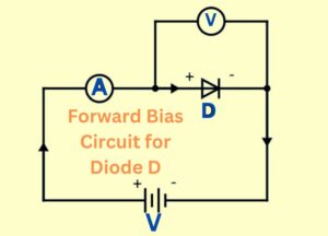
Forward biasing a diode means applying external voltage with the positive side connected to the diode's P-end and the negative side to the N-end. This makes it easier for electricity to flow by thwarting the diode's inherent resistance. It requires less voltage to overcome the obstruction because it lowers the resistance barrier and allows more charge carriers to pass through. As a result, current can flow continuously in one direction. In addition, the flow of electricity creates electron-hole pairs, which facilitate conduction in the P and N regions.
Simply put, forward biasing is like opening a one-way valve for electricity. Connect the battery to the diode in the right way, and it allows current to flow in the preferred direction. This principle is vital in electronics.
In a graphical representation, the battery's positive terminal aligns with the diode's positive connection, and the negative terminal coincides with the diode's negative connection. This arrangement underscores the significance of forward biasing in the operation of diodes, making it an indispensable principle in modern electronics.
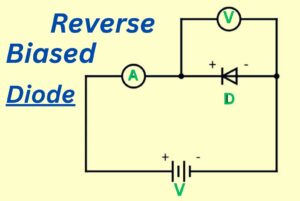
Reverse bias sets up a standoff, with the anode becoming negatively charged and the cathode positively charged. This forms a strong barrier, thickening the depletion layer, and boosting diode resistance. As a result, only minimal current can pass, creating a guard-like effect that prevents charge carriers from crossing until balance is restored. Forward bias welcomes current, while reverse bias resists it, akin to a strict guardian protecting voltage balance.
In electrical engineering, the half-wave rectifier is a clever circuit that transforms alternating voltage into steady direct voltage using just one diode. It selectively permits either the positive or negative half of the AC waveform to pass, creating a one-way current flow, turning AC into DC. However, it's less efficient, capturing only about 40.5% of the power compared to the more complex full-wave rectifier, which is twice as efficient. Despite its efficiency drawback, the half-wave rectifiers meaning remains a fundamental concept in electrical engineering, often needing capacitors to reduce ripples in the converted DC signal.
A full wave rectifier circuit can be realized in two ways: using a center-tapped transformer and two diodes, called a center-tapped full wave rectifier, or employing a standard transformer with four diodes arranged in a bridge configuration, known as a bridge rectifier. This discussion focuses on the center-tapped full wave rectifier meaning.
Unlike half-wave rectifiers that utilize only half of the AC cycle, full wave rectifiers take advantage of the entire cycle, offering higher efficiency. A step-down transformer is used to address high input AC voltage, converting it into low-voltage AC. During the positive half cycle, diode D1 forward-biases, while D2 reverse-biases, ensuring DC voltage is obtained for both polarities. Full wave rectifiers utilize four diodes, resulting in smoother output with less ripple, making them more efficient than half-wave rectifiers. This "bi-phase" circuit achieves 100% efficiency by rectifying both halves of each waveform cycle, providing a clean and stable DC supply.
By adjusting parameters such as reverse recovery time and voltage rating, engineers and designers can optimize diode performance for applications from power supply units to signal processing circuits Rectifier diodes, with their carefully tuned parameters, convert alternating current (AC) . to direct current (DC). play an important and useful role in a wide range of electronic devices, ensuring smooth and reliable flow of electricity.
Specifically, watts and volt-amperes are an integral part of electricity consumption, ensuring responsible energy consumption and system reliability. Knowledge of these categories allows individuals, engineers and businesses to make informed decisions, reduce waste and contribute to a more sustainable and efficient electricity future.
The temperature of a diode is important for how well it works. If it gets too hot, the diode might not work properly or could even break. This is why we need to make sure the diode doesn't get too hot. Especially in powerful devices, making heat is normal during the work of the diode what does it do. So, we need to use things like fans or metal pieces to take the heat away and keep the diode cool. Keeping an eye on the temperature and stopping it from getting too high is a must to make sure the diode works well and doesn't break because of the heat.
High current capacity is a crucial factor for rectifier diodes. It determines their ability to handle strong electrical currents while keeping rectification stable and efficient. Diodes designed for high-current tasks incorporate special features to handle these tough conditions.
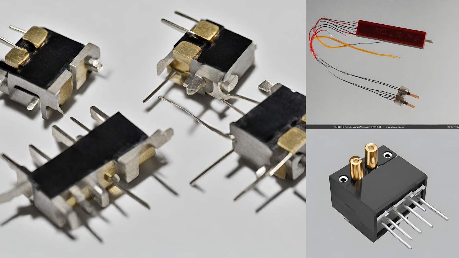
This involves using materials and designs that lower the voltage needed for forward flow and decrease power loss to avoid excess heat. What does a diode look like? High-current rectifier diodes are vital in power electronics, converting significant AC currents into DC for industrial and electrical systems, like power supplies and motor drives. Choosing diodes with the right current capacity is crucial to prevent overheating and ensure the system's longevity and safety.
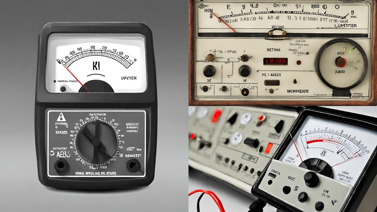
Using a digital multimeter, testing a rectifier diode is a somewhat easy procedure. Here's how to test a rectifier diode step-by-step:
Tools and Materials Needed:
Procedure:
Testing a rectifier diode using a digital multimeter is a straightforward process and can quickly identify if the diode is functioning correctly in both forward and reverse bias conditions.
You can also test a rectifier diode using an ohmmeter (also known as a resistance meter) on your digital multimeter. Here's how to do it:
Tools and Materials Needed:
Procedure:
Test a rectifier diode with an ohmmeter on your digital multimeter to assess forward and reverse resistance. Expected resistance means it's likely functional; otherwise, think about a replacement.
The VDC (Voltage Direct Current) measurement function is a crucial feature of multimeters and other electrical measurement devices. It allows you to measure and quantify the voltage of a direct current (DC) electrical source. Here's how the VDC measurement function of diode works:
To measure DC voltage with a multimeter:
Rectifier diodes find application in various electronic and electrical systems. what do diodes do - where the purpose of rectifier is conversion of alternating current (AC) to direct current (DC) is necessary. what is the purpose of diode - Here are some common rectifier diode applications:
These applications emphasize the versatility and importance of rectifier symbol, rectifier diodes in electronics, power systems, and industrial processes. They are essential functions of a diode defined or components for converting and controlling electrical power in a wide range of devices and systems.
In conclusion, rectifier diodes are vital in diverse electronic applications, converting AC to DC for powering devices. Now, we have a little bit idea about - definition of a rectifier, what is a diode rectifier? or what diode does? & The purpose of a diode in power supplies, chargers, autos, and industrial automation, ensuring efficient energy conversion. Their straight forward operation and AC voltage rectification make them indispensable in modern tech. As we advance in electronics and energy, rectifier diodes remain crucial for seamless power conversion in various applications, from consumer electronics to renewables and industrial machinery.
- What is P-type Semiconductor and N-type Semiconductor?
- Autumn Offer: Get $30 off PCB orders over $100 with NextPCB
- Free PCB Assembly Offer is Now Live
- HQ NextPCB Introduces New PCB Gerber Viewer: HQDFM Online Lite Edition
Still, need help? Contact Us: support@nextpcb.com
Need a PCB or PCBA quote? Quote now


 Surface