
 NextPCB Capabilities
Printed Circuit Boards
NextPCB Capabilities
Printed Circuit Boards
 PCB Assembly
 Layer Buildup
 SMD-Stencils
 PCB Design-Aid & Layout
 Mechanics
 Quality
 Drills & Throughplating
 Factory & Certificate
 PCB Assembly Factory Show
Certificate
PCB Assembly Factory Show
Certificate
Support Team
Feedback:
support@nextpcb.com


Table of Contents
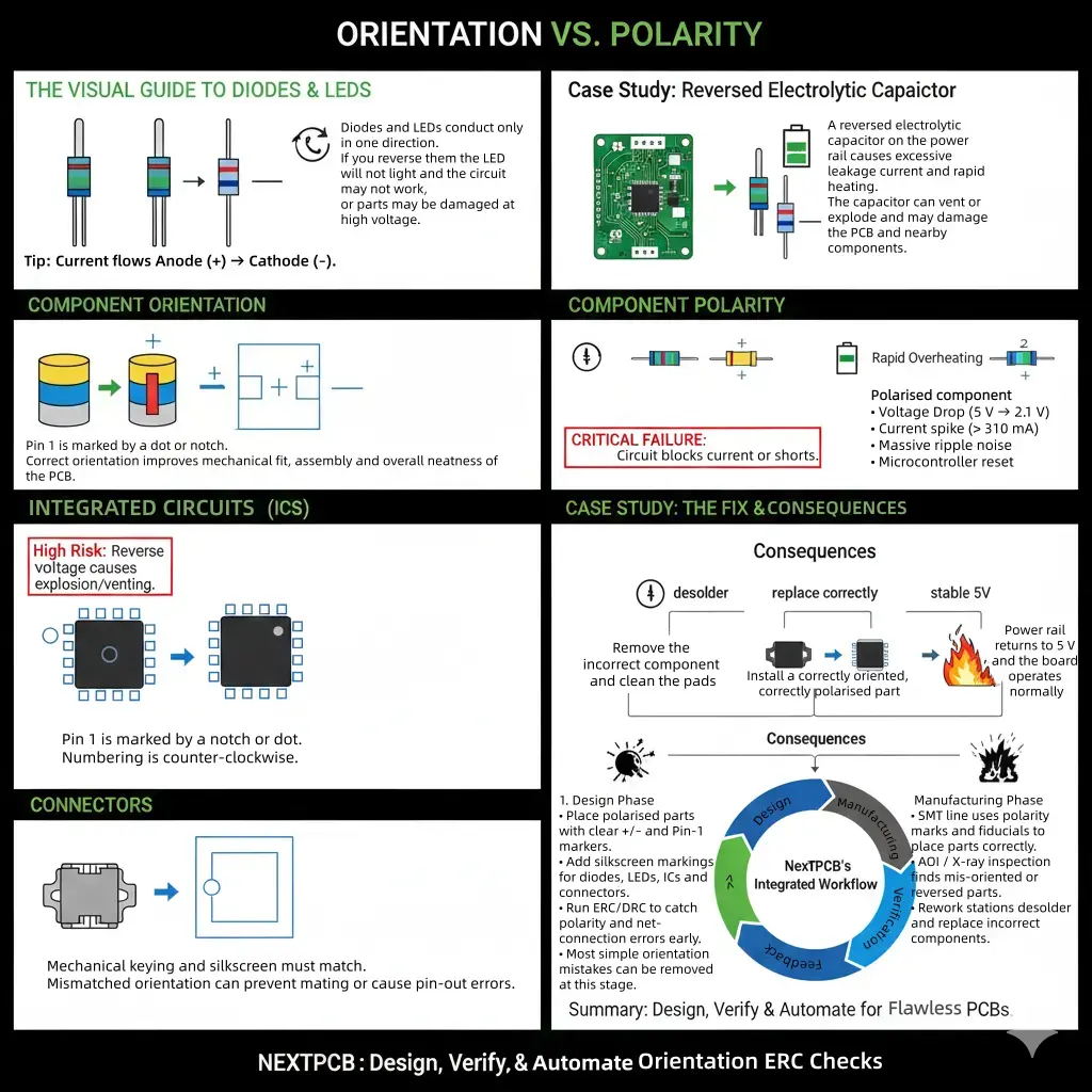
In PCB design and assembly, some of the most expensive and frustrating project failures come from mistakes that seem deceptively simple. Mistakes like misaligned components, reversed LEDs, an IC rotated 90 degrees, or a capacitor installed backward. These errors, often caused by incorrect component orientation or polarity, may look small on the board, but their impact can be massive. They could turn out to have blown circuits, unstable performance, delayed production, costly rework, and even complete board failure.
Component orientation refers to the physical direction a part is placed on the PCB. Polarity, on the other hand, determines how certain components must be electrically aligned for proper current flow. Together, they form the backbone of safe, functional, and manufacturable electronics. Whether you’re designing a simple sensor module or a multi-layer power system, mastering these two concepts is non-negotiable.
As electronics become smaller, denser, and more automated to assemble, orientation and polarity are no longer just “assembly concerns”—they are design decisions that directly influence manufacturability, testability, and long-term reliability. This is why understanding how to correctly place, label, and verify component direction is essential for every designer, from hobbyists to seasoned engineers.
In this article, we’ll break down the fundamentals of orientation and polarity, show you how to identify them across common components, walk through real-world mistakes and step-by-step solutions, and highlight best practices that ensure your designs pass through manufacturing smoothly, especially when sending them to professional services like NextPCB.
The article will help you understand how to avoid costly polarity errors and gain foundational clarity that will strengthen your grasp of circuit behavior—knowledge that seamlessly supports future topics, such as basic circuit components and transformations.
In PCB design and circuit engineering, “orientation” and “polarity” describe two distinct but interconnected parameters that determine how a component behaves electrically, mechanically, and during automated assembly. Although often used interchangeably by beginners, these terms have different engineering implications and failure modes. Understanding both is essential for accurate schematic interpretation, correct PCB footprint creation, reliable assembly, and predictable electrical behavior.
Component orientation refers to the physical direction or rotation of a part when placed on a PCB. Every component, polarized or not, has an intended orientation that ensures:
Even non-polarized components like resistors, ceramic capacitors, and ferrite beads benefit from consistent orientation. For example:
In short, orientation affects how the component fits, not how it conducts electricity.
Polarity refers to a component’s required electrical direction—that is, how it must be connected for current to flow correctly. Polarized components have distinct terminals (e.g., positive and negative, anode and cathode, pin 1 and pin 2) and will malfunction or fail if placed incorrectly.
Examples include:
Polarity is an electrical requirement, not just a physical one. It affects the fundamental operation of the circuit and determines whether voltage and current behave as designed.
| Aspect | Orientation | Polarity |
|---|---|---|
| Definition | Physical direction or rotation of a component on the PCB | Electrical direction required for correct current/voltage flow |
| Affects | Mechanical fit, pad alignment, assembly accuracy | Electrical behavior, safety, and circuit functionality |
| Applies to | All components (polarized and non-polarized) | Only polarized components |
| Examples | Connectors, IC alignment, resistor reading direction | Diodes, LEDs, electrolytic capacitors, transistors |
| Primary Risk if Incorrect | Misalignment, improper mating, AOI failures, rework | Component failure, overheating, short circuits, catastrophic damage |
| How Identified | Silkscreen outlines, pin-1 indicators, and connector keys | +/− marks, cathode bands, notches, body labels |
| Electrical Impact | Usually, none unless misalignment affects pin routing | Always affects circuit behavior—100% critical |
Non-Polarized Components: These parts can be placed in either direction without affecting their electrical behavior:
These components are excellent for teaching basic circuit concepts because their function stays the same regardless of orientation.
Polarized Components: These devices have direction-dependent electrical behavior, determined by their internal construction.
Their correct orientation is non-negotiable. Misplacing them leads to short circuits, reverse currents, excessive heating, and potentially catastrophic failure.
| Component Type | Typical Examples | Are They Direction-Sensitive? | How to Identify Correct Orientation/Polarity | What Happens If Installed Incorrectly? |
|---|---|---|---|---|
| Non-Polarized Components | Resistors, ceramic capacitors (MLCCs), inductors, ferrite beads | No (electrically) | Orientation is optional, but aligning consistently helps AOI and readability | Usually, no electrical failure; worst case is assembly confusion |
| Polarized Capacitors | Electrolytic caps, tantalum caps | Yes—strict polarity | +/− labels, long/short leads, stripe marking, square PCB pad | Overheating, bulging, venting, explosion, rapid degradation |
| Diodes & LEDs | Rectifier diodes, Zener diodes, indicator LEDs | Yes—conduct only one way | Cathode band, PCB diode symbol, lead length, flat edge on LED lens | Circuit malfunction, reverse blocking, LED not lighting, diode shorting |
| Transistors | BJT (E/B/C), MOSFETs (G/D/S) | Yes | Pinout orientation, package notch, manufacturer marking | Device burnout, incorrect biasing, full circuit failure |
| Integrated Circuits (ICs) | MCUs, op-amps, regulators, drivers | Yes | Pin-1 dot, notch, chamfered edge, square PCB pad | Reverse pin mapping → immediate component destruction |
| Polarized Connectors | USB ports, pin headers, keyed sockets | Yes (mechanical + electrical) | Keying, notch direction, pin-1 marking | Incorrect mating, shorts, reversed signal routing |
Component orientation and polarity may seem like small details, but in PCB design and manufacturing, they determine whether a board functions reliably—or fails catastrophically. Both concepts influence electrical behavior, thermal performance, assembly precision, and even long-term product safety. This section explains the engineering logic behind why orientation and polarity must be strictly controlled.
Electrical behavior is governed by the correct direction of current flow, voltage referencing, and impedance paths. When polarized components such as diodes, MOSFETs, or electrolytic capacitors are reversed, their internal structures (PN junctions, dielectric layers, or transistor regions) experience unintended electrical stress.
Correct polarity ensures:
Incorrect orientation disrupts current paths, forcing the circuit into unintended operating regions, which may trigger oscillation, reverse conduction, or complete failure to power up.
Polarity mistakes are one of the fastest ways to damage a circuit. Common failure modes include:
Even if the board powers up, reversed components often suffer latent degradation, meaning they fail days or months later. This is an unacceptable risk in consumer electronics, automotive systems, and medical devices.
Modern PCB factories use automated systems, pick-and-place, solder reflow, and AOI, which rely on accurate orientation data. Incorrect rotation in the PCB footprint or component library leads to:
Since each misalignment requires manual rework, polarity errors rapidly increase production cost and turnaround time—something NextPCB helps engineers minimize through strict DFM checks.
Even minor orientation errors can cause long-term reliability problems:
A board assembled with perfect polarity is easier to repair, diagnose, and update—especially in regulated industries where documentation and traceability matter.
Recognizing polarity and orientation markings is one of the most essential skills in PCB design and assembly. Every component type—especially the most commonly used ones like diodes, LEDs, capacitors, transistors, and ICs—has specific visual cues on both the component body and the PCB footprint that guide proper placement. Misreading these markings can result in reversed current flow, damaged parts, or costly rework. The guide below provides an engineering-focused breakdown of how to identify orientation across these commonly used PCB components.
Diodes and LEDs are inherently directional because they contain a PN junction that conducts in only one direction. Their polarity is identified through:
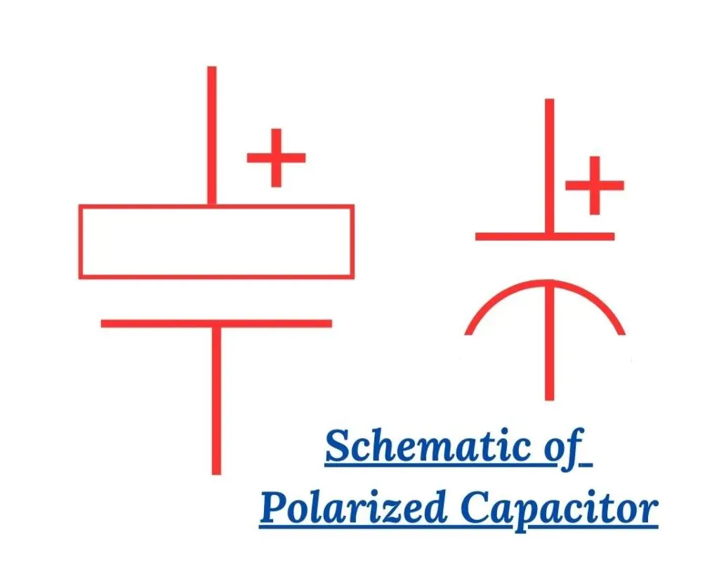
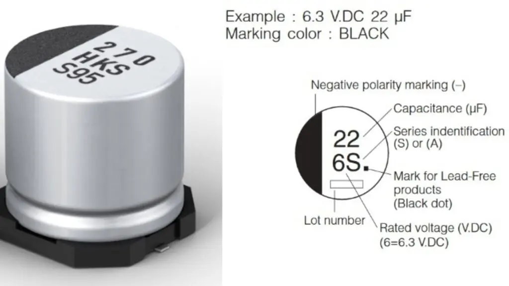
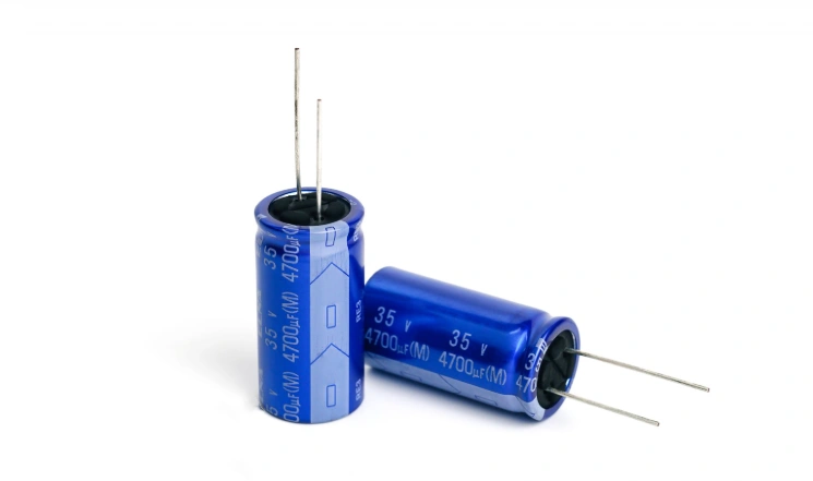
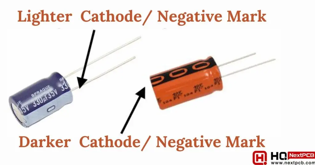
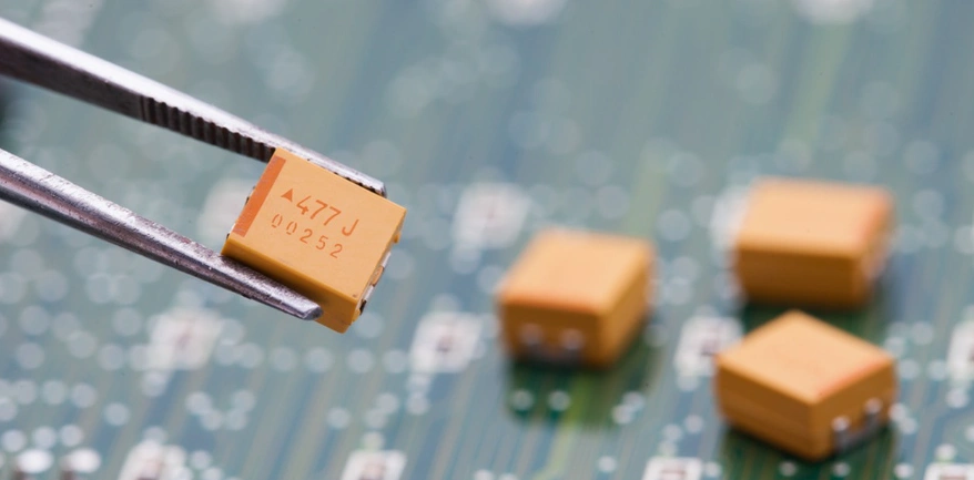
Polarized capacitors must follow strict polarity to avoid thermal runaway or explosion. Key identifiers include:
Electrolytic capacitors:
Tantalum capacitors:
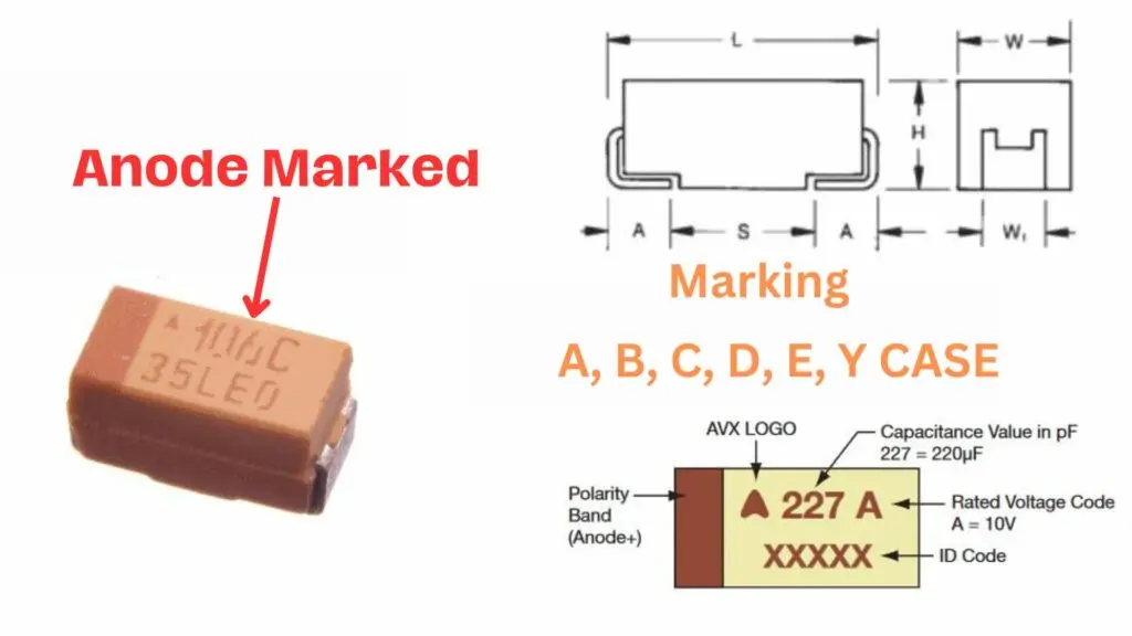
On the PCB footprint:
Understanding common components on a PCBA and what matters in assembly gives a broader light to why these polarity cues matter during automated assembly and AOI.
ICs rely on a standardized Pin 1 reference, and incorrect rotation is almost always fatal to the device.
Pin 1 is identified through:
Correct IC orientation is essential because pin assignments for power, ground, I/O, and clocks depend entirely on the Pin 1 position.
Small SMD packages—resistors, capacitors, diodes, transistors—often include subtle orientation indicators:
A more comprehensive understanding involves examining PCB SMD components in detail, particularly their classifications and identification methods. It will clarify how SMD markings differ across package families and provide a structured approach to recognizing them.
While not electrically polarized in the same way as diodes are, connectors and switches have mechanical polarity. Their orientation determines how users interact with the product.
Key identifiers include:
Incorrect orientation can reverse power rails, misalign interfaces, or break mechanical mating, making these components just as critical as their polarized counterparts.
Polarity errors occur even in well-designed circuits—often due to mixed manufacturer markings, flipped footprints, or rushed hand assembly. This case study walks through a real-world scenario involving a reversed electrolytic capacitor on a power rail. It demonstrates how polarity errors are detected, diagnosed, and permanently resolved in both prototyping and mass production.
A small DC motor controller board was assembled and tested. Upon powering the board:
Initial suspicion included a short on the 5 V line, a regulator failure, or excessive load. However, the rapid heating near the power-entry electrolytic capacitor pointed to a potential polarity issue.
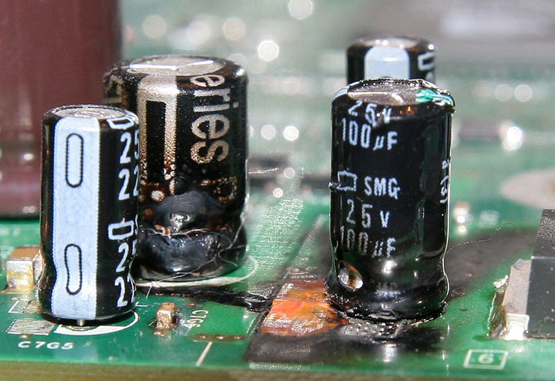
The technician examined the capacitor and noticed:
In many factories, this error is caught by Automated Optical Inspection (AOI), which compares the outline and polarity cues against the expected polarity stored in the pick-and-place program.
Multimeter tests revealed:
Reverse-biased electrolytic capacitors begin to heat internally because the dielectric layer breaks down, leading to escalating current leakage. This confirmed a classic polarity reversal failure.
The technician:
On retesting:
To avoid repeated mistakes, the team implemented:
A professional assembler like NextPCB typically applies these checks automatically, making polarity-related defects extremely rare in mass production.
This simple polarity reversal caused heat buildup, regulator instability, excess current draw, and near-failure of the entire board. Yet the root cause was a single incorrectly oriented component.
Understanding polarity markings, validating footprints, and relying on consistent DFM processes eliminates these errors—saving time, components, and production cost.
Correct component orientation is not just an assembly detail. It directly influences electrical performance, board reliability, repairability, and overall product quality. These best practices help engineers and manufacturing teams build PCBs that function reliably under real-world conditions.
NextPCB integrates a multi-layer Design for Manufacturability (DFM) workflow that significantly reduces the risk of polarity or orientation mistakes during assembly. NextPCB’s engineers perform a three-way cross-check between your Gerber files, BOM, and CPL (centroid/position file) to ensure that component footprints, polarity indicators, and rotation values all match correctly. During production, Automated Optical Inspection (AOI) machines verify polarity marks, cathode bands, pin-1 indicators, and silkscreen alignment in real time. If the system detects any anomaly—such as a rotated LED, mismatched pad marking, or unclear polarity label—NextPCB’s team performs a manual engineering review before continuing to mass production. This combined automated and human validation ensures that even subtle orientation issues are caught early, preventing costly failures later in the product lifecycle.
What happens if I install an electrolytic capacitor backwards?
Reversing an electrolytic capacitor forces current to flow through it in the wrong direction. This causes rapid heating, internal gas buildup, leakage, and in extreme cases, venting or explosion. Even if it doesn’t fail instantly, its lifespan is significantly reduced, making reversal one of the most dangerous polarity mistakes in PCB assembly.
How can I quickly identify the polarity of a diode or LED?
Diodes and LEDs almost always use two indicators:
For LEDs, the longer lead is typically the anode (+) and the flat edge of the LED lens marks the cathode (−). On SMD LEDs, a green triangle or dot typically marks the cathode.
Are ceramic capacitors polarized?
No. Ceramic capacitors (MLCCs) are non-polarized and can be placed in either direction without affecting electrical behavior. However, manufacturers still recommend consistent orientation to help AOI systems detect tombstoning, rotation, or placement defects during reflow.
How do I find pin 1 on an IC?
Pin 1 is usually marked by:
The PCB footprint should also include a square pad or a pin-1 indicator on the silkscreen. Aligning these two signals prevents catastrophic misrouting of internal power and signal pins.
Can reversing a diode damage a circuit?
Yes—especially in power paths. A reversed diode may:
Always verify polarity markings during assembly and testing.
Why are connectors considered “polarized components”?
Connectors often have mechanical keying, notches, chamfers, or pin-1 directionality. Incorrect orientation can misalign signals, short adjacent pins, or mechanically prevent proper mating. For external-facing connectors (USB, headers, sockets), orientation also affects usability and product safety.
Component orientation and polarity are often overlooked details, yet they sit at the core of reliable PCB design and manufacturing. From diodes and electrolytic capacitors to ICs, connectors, and miniature SMD parts, each component has a specific direction that determines how current flows, how signals behave, and how safely the board operates. A single misalignment can cause anything from subtle performance issues to catastrophic failures—including overheating, short circuits, or total board damage.
By combining clear PCB markings, accurate schematic-to-layout alignment, robust AOI inspection, and close collaboration with manufacturers like NextPCB, engineers can significantly reduce assembly errors and improve long-term product performance. Practical workflows—such as prototype verification, maintaining precise part libraries, and following standardized land-pattern conventions—further ensure that orientation and polarity are consistently correct across the entire board lifecycle.
In a world where electronic products are becoming more compact, more complex, and more interconnected, small details matter more than ever. Paying close attention to component direction is one of the simplest yet most powerful ways to build PCBs that are safe, efficient, and dependable—from the prototype to full-scale production.
Get BOM Services Engineer Consultation
About the Author
Abiola Ayodele: Broadcast Journalist & Tech Writer; Cooperate writer of NextPCB.
Specialize in technical writing, and editing, particularly in the areas of PCB design, semiconductors, cybersecurity, and emerging engineering technologies.
Still, need help? Contact Us: support@nextpcb.com
Need a PCB or PCBA quote? Quote now


 Surface

