
 NextPCB Capabilities
Printed Circuit Boards
NextPCB Capabilities
Printed Circuit Boards
 PCB Assembly
 Layer Buildup
 SMD-Stencils
 PCB Design-Aid & Layout
 Mechanics
 Quality
 Drills & Throughplating
 Factory & Certificate
 PCB Assembly Factory Show
Certificate
PCB Assembly Factory Show
Certificate
Support Team
Feedback:
support@nextpcb.com


Diodes are electronic components that play a fundamental role in modern technology. This is a simple device that allows current to flow in one direction while blocking it in the opposite direction. This property makes them ideal for a wide range of applications, from power supply circuits to digital electronics. Assemble a diode by sandwiching two semiconductor materials, such as silicon or germanium, around a p-n junction.
In doing so, you'll have crafted an effective and reliable electrical component that regulates the direction of current flow. By introducing impurities, this junction can be built by satisfying the side of the semiconductor with an abundance of electrons (n-type) and depleting it from its counterpart that needs a deficiency in electrons (p-type). The designers of avalanche diodes enabled current flow by making them operate in reverse breakdown mode, which requires a set voltage to be provided.
Applying a forward voltage sparks an energetic exchange between its n-type and p-type regions, with electrons rushing from one side of the junction to the other as their positive counterparts make a beeline in reverse. As a result, the depletion region narrows and eventually disappears, allowing current to flow through the diode.
The application of a reverse voltage across a diode causes the depletion region to widen. Thereby inhibiting the flow of current in the opposite direction. This property is what makes diodes so useful for rectifying AC signals into DC signals. Moreover, for protecting sensitive components from voltage spikes.
With an expansive array of diverse diodes, each with its own unique characteristics and uses, the possibilities are endless! Rectifier diodes are powerhouses, capable of managing hefty amounts of current and voltage. And zener diodes act as guardians for your circuits. By keeping the electrical flow within its designated limits.
Diodes are an essential part of many electronic devices, from supporting the flow of electric current in amplifiers to regulating. Diodes act as unidirectional conductors, allowing current to flow in a predetermined direction and blocking it in the opposite direction. Because of this property, diodes find applications in diverse fields, ranging from lighting technology to power supplies. Diodes are a versatile and essential component of many electronics.
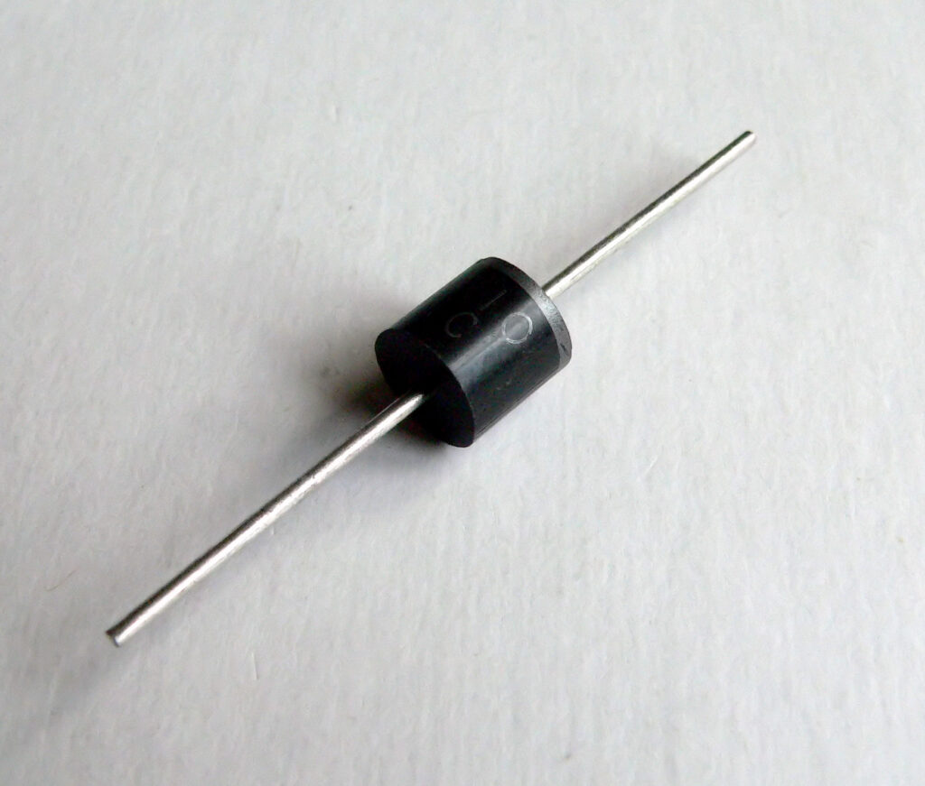
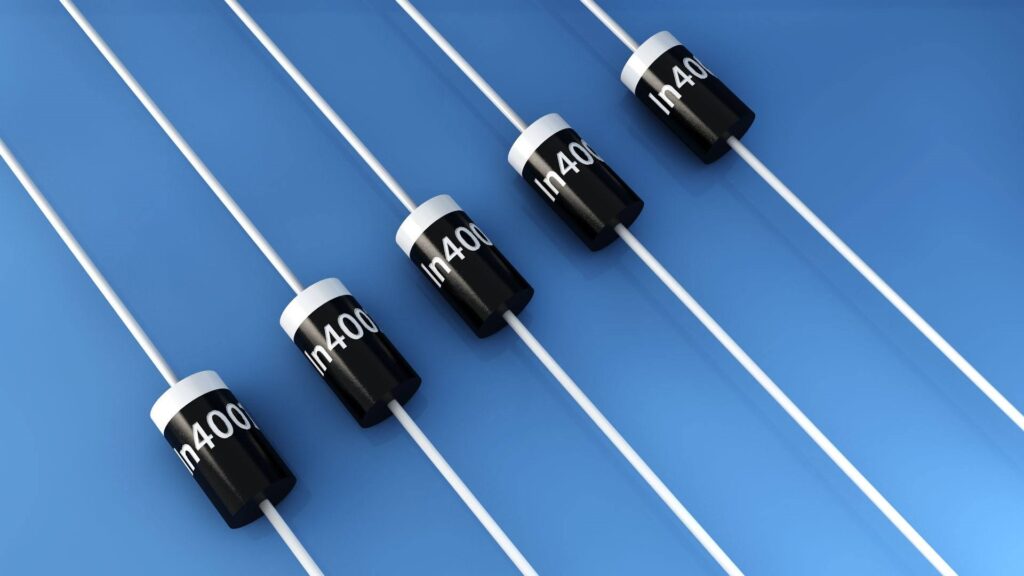
Rectifier diodes are one of the most common types of diodes. In power supply circuits, people use diodes to convert AC (alternating current) to DC (direct current). A rectifier diode consists of a P-N junction, which allows current to flow in only one direction. Rectifier diodes are a type of electronic device that sift through alternating current waveforms to control the flow of electricity. They come in two distinct forms - half-wave and full-wave rectifiers. Each with an important role to play in regulating power throughout your circuit.
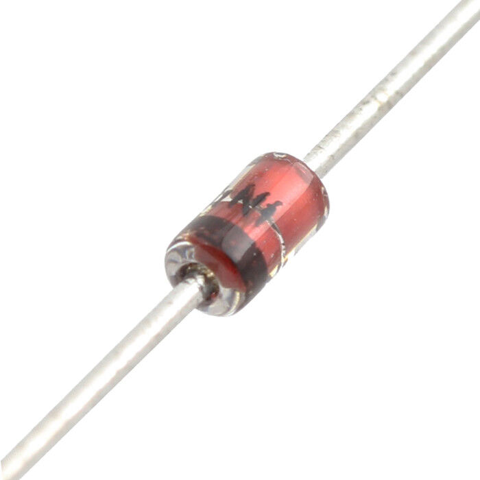
Zener diodes operate in the reverse breakdown region. By allowing them to conduct current in the reverse direction when a certain voltage is applied. In electronic circuits, Zener diodes act as voltage regulators. In order to maintain a stable voltage output despite changes in input voltage or load.
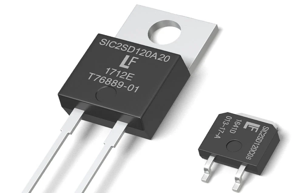
The metal-semiconductor junction is used in the construction of Schottky diodes. This allows for faster switching and lower voltage drop compared to other types. High-speed switching components such as power supplies and RF circuits generally use Schottky diodes.
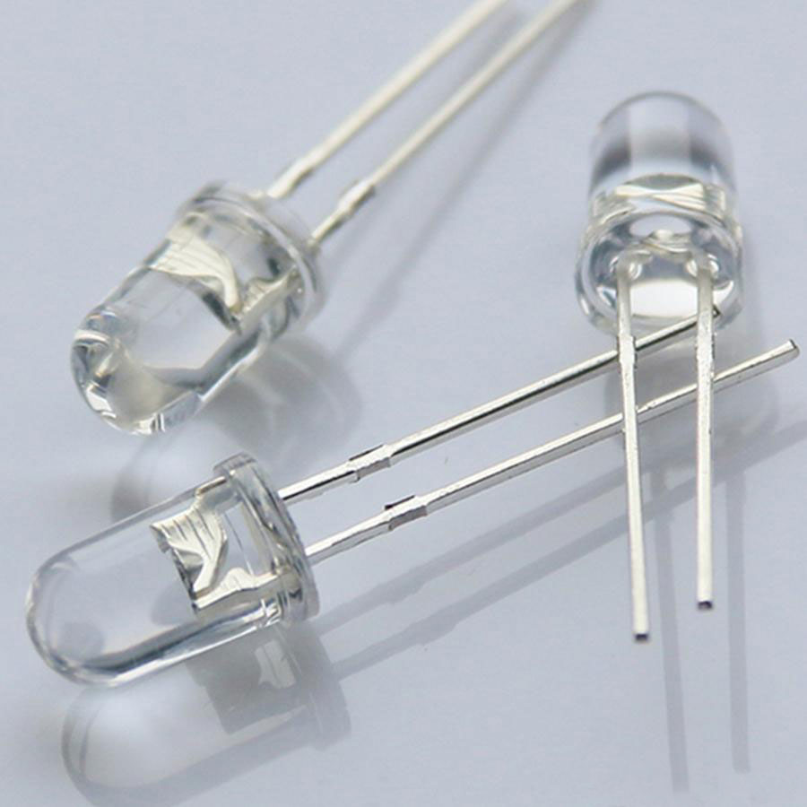
LEDs are an incredibly versatile source of light, providing dependable illumination for everything from everyday activities to city-wide traffic signals.
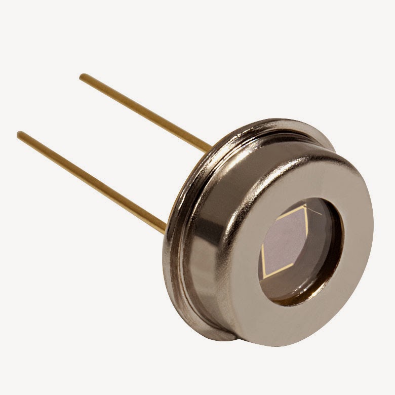
The main purpose of photodiodes is to convert light energy into electrical current. Photodiodes have a wide range of applications, including optical communication systems, such as fiber optics, light sensors, and cameras.
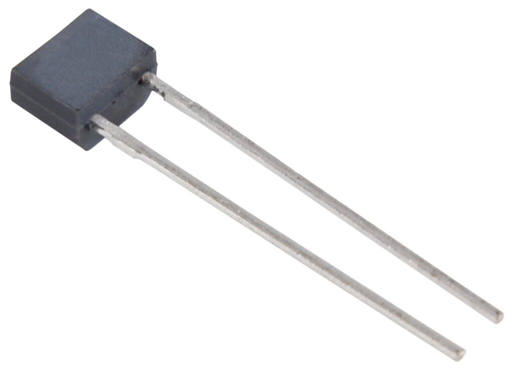
Tuning circuits, such as those found in radio and television receivers, use varactor diodes, which are also known as variable capacitance diodes. By altering the electrical capacity of a diode in relation to voltage, we can manipulate its resonant frequency and use this capability for various purposes.
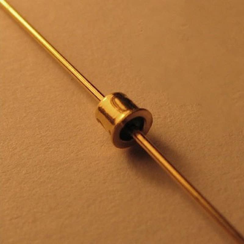
The designers of tunnel diodes made them operate in the negative resistance region, enabling them to conduct current more easily when the voltage across them decreases.
The designers of avalanche diodes made them operate in reverse breakdown mode. This enables current to flow when a set voltage is provided. Such components find use in high-voltage systems such as power supply networks and electric surge protection apparatus.
Understanding the different types of diodes and their respective applications is key to making the decision when selecting one.
The function of diodes in electronic circuits is to allow the transmission of electricity in one direction while blocking its flow in the opposite direction, making them an essential component of such circuits. With two terminals - namely the anode and cathode - these integral components help make modern technology possible! Understanding diode polarity is crucial to correctly connecting it in a circuit and avoiding damage to the device or the circuit.
The anode is the positive pole, while its negative counterpart - the cathode - serves as its negative terminal.
A diode's polarity holds great importance - inserting it the wrong way will prevent proper functionality, possibly causing damage to your circuit or device. It pays off to be mindful of that crucial detail! This is because diodes have a specific breakdown voltage, which, when exceeded, causes it to fail or become permanently damaged.
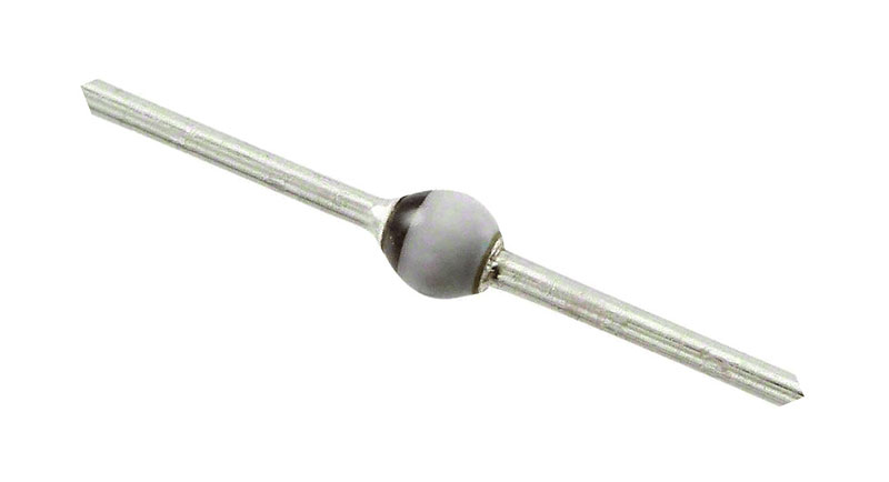
One of the simplest ways to determine the polarity is to look for identifying marks on the diode itself. Most diodes have a stripe or a band around one end of the device, which indicates the cathode terminal. On certain diodes, you may notice the letters "A" or "K", which signify the anode and cathode respectively..
So, understanding its polarity is essential to correctly connect it to a circuit and avoid damage to the device or the circuit. Diodes have a specific breakdown voltage, and exceeding this voltage may cause permanent damage to the diode. Identifying marks on the diode itself or using a multimeter are the simplest ways to determine the diode's polarity
Diagnosing a diode is of utmost importance; it guarantees that the device is constructed as expected and executes its assigned purpose in an electronic circuit. An ineffective or impaired diode can result in different issues, for instance, network breakdowns, wrong voltage readings, and reduced performance.
Here are a few reasons why testing is important:
So, testing a diode is an important step in maintaining the proper functioning of electronic circuits and preventing potential damage or failure.
To test a diode, you will need the following tools and equipment:
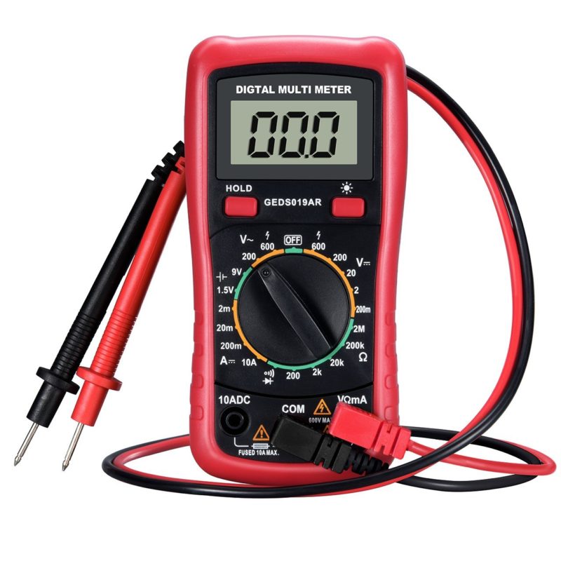
Having these tools and equipment on hand will make testing a diode much easier and more accurate.
Performing a basic continuity test on a diode is a simple process that can help you determine if the diode is functioning correctly. Here are the steps to follow:
Reverse the test leads and touch the black lead to the anode and the red lead to the cathode.
Check the multimeter display again. If the diode is functioning correctly, the multimeter will not beep and may show a reading of infinity. If the diode is faulty or damaged, the multimeter will not beep and may show a reading of zero ohms.
And if the diode passes the continuity test in both directions, it is likely functioning correctly. However, a basic continuity test only checks for a low-resistance path through the diode, and it does not provide information about the diode's voltage drop or other characteristics.
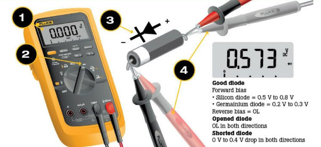
Performing a voltage drop test on a diode can help you determine if it is functioning correctly and allowing current to flow in the correct direction. Here are the steps to follow:
It's important to note that voltage drop tests only work on diodes that are already in connection with a power source. Additionally, this test only checks for the forward voltage drop and does not provide information about the diode's reverse characteristics or other parameters.
If the diode passes the voltage drop test in both directions and other tests show that it is functioning correctly, it is likely working properly in the circuit. However, if the diode fails the voltage drop test or other tests, it may be faulty or damaged and need a replacement.
A reverse voltage test is a method used to check if a diode blocks current flow when connected in the reverse direction. Diodes are designed to conduct current in one direction and block current in the opposite direction, so testing the diode's reverse voltage characteristics is important to ensure it is functioning properly.
To perform a reverse voltage test on a diode, follow these steps:
By performing a reverse voltage test, you can ensure that it is functioning properly and blocking current flow in the reverse direction.
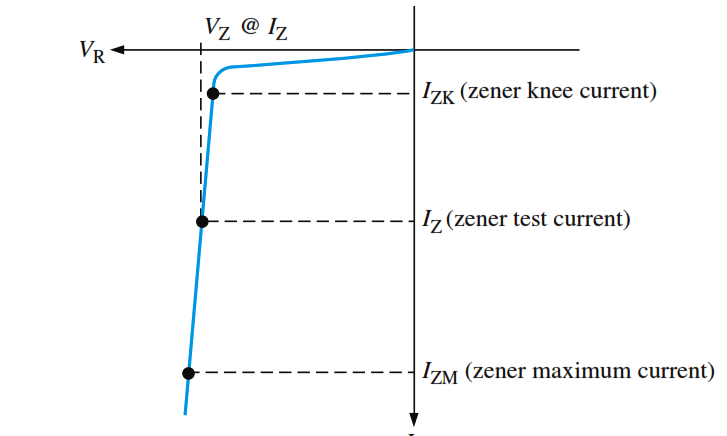
A Zener breakdown test is a method used to check the voltage at which a Zener diode starts to conduct in the reverse direction. Zener diodes are designed to operate in the reverse breakdown region, and this characteristic is important in applications such as voltage regulation or voltage reference.
To perform a Zener breakdown test on a Zener diode, follow these steps:
By performing a Zener breakdown test, you can ensure that the Zener diode is operating in its intended breakdown region and providing the desired voltage regulation or reference. It is important to note that Zener breakdown testing should be performed only by experienced professionals with proper equipment and safety precautions, as high voltages are involved.
Diodes are simple electronic components that can fail for various reasons, causing issues in the circuit they are used in. Here are some common diode problems and how to troubleshoot them:
An open diode is one that has failed completely and is not allowing any current to pass through it. This can cause the circuit to fail or operate erratically. To troubleshoot this issue, use a multimeter to test the diode's continuity.
If you observe OL or a high reading in both directions on the multimeter, it indicates that it is in open condition and requires replacement.
A shorted diode is one that has failed and is allowing current to flow in both directions. This can cause the circuit to fail or operate erratically. To troubleshoot this issue, use a multimeter to test the diode's continuity.
If you observe a low reading or a voltage drop in both directions on the multimeter, it indicates that the component is in short condition and requires replacement.
A reverse-biased diode is one that is connected backward in the circuit, causing it to block current flow in both directions. This can cause the circuit to fail or operate erratically. To solve this issue, you need to verify the placement of the diode in the circuit and make sure that you connect its cathode to the negative side of the power supply and its anode to the positive side.
An overheated diode can occur due to excessive current or voltage in the circuit, causing the diode to fail or become damaged. To troubleshoot this issue, inspect for physical damage, such as cracks or discoloration. Additionally, you should check the circuit for excessive current or voltage and confirm that the diode is appropriately rated for the circuit.
Using the incorrect type can cause issues in the circuit, such as excessive voltage drop or current leakage. A multimeter allows you to test diodes and perform both continuity and voltage drop tests, making it a useful tool.
If the diode is incorrect, replace it with the appropriate type.
Additionally, performing regular testing and maintenance on the circuit can help identify and address issues before they cause larger problems.
In conclusion, testing is an important step to ensure the proper functioning of electronic circuits. A multimeter proves to be a useful tool as it allows you to test diodes and perform both continuity and voltage drop tests. You can use a multimeter for testing diodes and performing continuity and voltage drop tests, making it a useful tool.
It is important to test in the correct orientation and to take proper safety precautions when testing with high voltages.
By understanding the different testing methods and how to troubleshoot common problems, electronics professionals can ensure the reliable operation of electronic circuits and prevent potential damage to other components in the circuit.
Still, need help? Contact Us: support@nextpcb.com
Need a PCB or PCBA quote? Quote now


 Surface

