

 NextPCB Capabilities
 PCB Assembly
 Layer Buildup
 SMD-Stencils
 PCB Design-Aid & Layout
 Mechanics
 Surface
 Quality
 Drills & Throughplating
 Factory & Certificate


Introduction: From Images to Intelligent Models—The Revolution in PCB Data Exchange
[Latest Version Information]
Latest Version (As of 2025-10-10): IPC-2581 Revision C (Released November 2020). This revision introduces bilateral DfX/DFM data exchange capabilities, significantly strengthening the digital expression of manufacturing intent for rigid-flex, embedded components, plating, and hole types. It also allows precise definition of controlled impedance and identification of differential pairs at the net, layer, and stack-up levels.
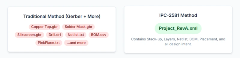
In the modern electronics manufacturing industry, which constantly pursues high precision and high speed, efficiency and accuracy are key determinants of successful product launch. However, the traditional method of PCB data exchange—relying on fragmented, non-intelligent Gerber files and numerous auxiliary documents—has become a serious bottleneck to hardware iteration speed. This fragmented data flow leads to high manual verification costs, prolonged New Product Introduction (NPI) cycles, and increased error risk, severely impacting the operational efficiency of small-to-medium hardware companies and EMS/Contract Manufacturers seeking flexible capacity.
To address this industry pain point, IPC-2581 (Digital Product Model eXchange, IPC-DPMX) was created. It is no longer just a collection of digital images but a revolutionary, unified, and vendor-neutral smart data standard. The core value of IPC-2581 lies in encapsulating all necessary information for PCB fabrication, assembly, and testing, including complex stack-up structures, controlled impedance specifications, netlists, and BOMs, all within a single XML file.
For NPI and Process Engineers, IPC-2581 translates to automated and accelerated Design for Manufacturability (DFM) processes, ensuring the manufacturing precision of complex designs (such as back drills and differential pairs). For Procurement aiming for cost efficiency and firm deadlines, this unified data package significantly reduces communication errors and prototyping iterations.
This article will delve into the core advantages of IPC-2581, compare it against traditional Gerber and ODB++, and provide practical application guidelines to help you transition from traditional to smart manufacturing.
I. Moving Beyond Traditional Pain Points: Why NPI Engineers Need to Embrace IPC-2581
In the era of rapid electronic product iteration, the speed and accuracy of the NPI process directly determine a hardware company's market competitiveness. Traditional PCB data exchange often acts as a major bottleneck causing inefficiency between design teams and manufacturing partners. IPC-2581 emerged precisely to solve these pain points, paving the way for a "Digital Thread" leading to smart manufacturing.
1.1 What is IPC-2581? The Future of PCB Smart Data Exchange
IPC-2581, officially known as Digital Product Model eXchange (IPC-DPMX), is a standard designed to provide a unified data format for describing Printed Circuit Boards (PCBs) and their assemblies. Its core goal is to enable seamless data exchange between designers and manufacturers, completely replacing the traditional model that relies on multiple fragmented files.
The most prominent feature of the standard is its data structure: all essential PCB manufacturing details (such as layer stack-up, copper artwork, drill data), assembly information, BOM, and netlist are integrated into a single XML file. Compared to the multi-file or multi-directory packaging methods of Gerber/ODB++, IPC-2581 achieves unified data coverage. The adoption of XML offers a huge advantage. It provides a systematic organizational structure, making data easier to read, understand, and machine-parse, thereby significantly reducing data processing complexity. This unified, intelligent file format allows CAM tools to directly accept and interpret the data, eliminating the need for extensive manual intervention during the data preparation phase, which is crucial for small-to-medium hardware companies seeking fast NPI cycles.
In fact, adopting IPC-2581 is not just about changing a file format; it is a critical step in driving factories toward Industry 4.0 and smart manufacturing. A single, structured data source allows advanced Manufacturing Execution Systems (MES) and automated DFM tools to analyze and process orders, providing manufacturers with a basis for rapid and flexible capacity, better serving procurement seeking clear deadlines and cost objectives. The IPC-2581 file is no longer a collection of simple image data but a complete digital description of the final physical PCB board.
1.2 The Predicament of Traditional Data Packages: NPI Risks Associated with Gerber Files
For a long time, the Gerber format has been the mainstream standard in PCB fabrication. Gerber files are the digital blueprints of a PCB design, using an open ASCII vector format to describe the physical properties of each layer on the board. However, Gerber is inherently an image format, which imposes structural limitations on its data intelligence.
Traditional Gerber data packages require the design team to provide multiple separate files, including aperture files, parameter files, artwork files, and DRL drill files. A more serious issue is data fragmentation and the lack of association: the Netlist, Bill of Materials (BOM), and Pick-and-Place data must often be provided to the manufacturer as unrelated, independent documents (such as PDFs, Excel spreadsheets, or text files).
This fragmentation leads to high-risk manual verification steps. The manufacturer's Computer-Aided Manufacturing (CAM) department must dedicate significant time to "Non-Recurring Engineering" (NRE), manually reconstructing the design intent from image data, such as defining the PCB board stack-up, extracting, and verifying the netlist. Due to the lack of a mechanism to enforce consistency between these disparate files and the PCB layout data, NPI and Process Engineers must perform time-consuming and error-prone manual DFM checks and data reconciliation to prevent common errors like design mismatches, insufficient clearances, or unregistered layers. This process of data reconstruction, manual verification, and repeated communication significantly extends the NPI cycle, increasing manufacturing costs and the risk of errors—hidden costs that are ultimately passed on to startups seeking flexible capacity and cost efficiency.
- Although IPC-2581 is the future, rapid file accuracy verification is vital in processes still relying on Gerber files. You can try NextPCB's Online Gerber Viewer Tool. It quickly renders the multiple files you upload, helping you instantly and visually identify basic issues like layer misalignment or dimensional inconsistencies, serving as a crucial aid for rapid preliminary inspection in traditional NPI workflows.
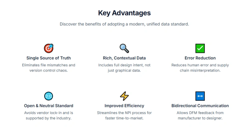
II. IPC-2581 Core Advantages: The All-in-One Smart Data Package
By consolidating all design intent and manufacturing details into one "smart data package," IPC-2581 solves the inherent fragmentation problem of the Gerber format, leading to a revolutionary increase in efficiency for PCB fabrication and assembly.
2.1 Complete Data Integration: Bidding Farewell to "Scattered Files"
The core advantage of IPC-2581 is its data completeness. It uniformly packages all information required for PCB fabrication, assembly, testing, and procurement into a single XML file. This integrated content includes, but is not limited to: layer data, drill data, the complete netlist information, Bill of Materials, test pad locations, and detailed design variants and assembly properties (such as component designators and part numbers).
This unified packaging is particularly important for NPI Engineers. In traditional processes, inconsistencies between the BOM (used by Procurement) and the placement data (used by Assembly) are major causes of assembly errors. IPC-2581 fundamentally eliminates this risk because it ensures that part numbers, component designators, and placement parameters are interlinked and consistent within the data file. This means the BOM used for procurement and the machine file used for assembly are based on the same data source, greatly reducing cross-department communication barriers and human error.
Furthermore, the standard also ensures targeted and secure data transmission. When exporting an IPC-2581 file, the user can precisely and selectively suppress data not needed for a specific purpose (e.g., only fabrication is needed, not procurement information), ensuring the precision and minimal transmission principle of the data.
2.2 Addressing Highly Complex Designs: Key Advances from Revisions
As modern electronics demand increasingly high-speed, high-density, and high-layer count PCBs, IPC-2581 is continuously revised to meet the requirements of cutting-edge technology.
IPC-2581 Rev B (Drill Specification Enhancement)
Revision B improved functionality for drilling and drill types, allowing design teams to provide more detailed drill datasets. Most notably, it supports Back Drilling specifications. For high-speed signal design, back drilling is a critical technique for eliminating signal stubs to ensure Signal Integrity (SI). Rev B allows precise definition of back drilling requirements within the Layer Stack section of the design data file, including: back drill diameter, precise back drill depth, location (specified through coordinates or referencing other features), and optional plating requirements. These precise physical parameters directly guide the mechanical processing of the PCB, ensuring the elimination of physical stubs on high-speed traces, thereby maintaining the quality of signal transmission on the physical circuit board. Embedding these complex parameters directly into the data file, rather than relying on fabrication notes or drawings, significantly enhances manufacturing accuracy and first-pass yield.
IPC-2581 Rev C (High-Frequency Design Cornerstone)
Revision C further solidified IPC-2581's core position in high-frequency and high-performance design. Rev C enables the precise definition of Controlled Impedance specifications. Designers can now stipulate detailed impedance requirements at the net, layer, or even stack-up levels.
For complex Radio Frequency (RF) and high-speed digital circuits, Rev C can also explicitly identify differential pairs. This definition capability is crucial because it directly embeds the PCB's electrical performance requirements into the manufacturing data. Manufacturers can use this embedded data to automatically adjust physical manufacturing parameters such as copper thickness, dielectric material selection, and trace geometry, ensuring that the final circuit board strictly meets signal integrity specifications, such as differential line requirements. This shifts complex SI requirements from error-prone manual communication to automated machine verification, providing a solid guarantee for the successful fabrication of high-layer count, high-frequency boards.
Furthermore, the standardized definition of stack-up information in the IPC-2581 format is a key advantage. It includes all necessary information such as layer names, sequence, material thickness, dielectric constant, conductive and coating material characteristics, and tolerances. This information collectively forms the "skeleton" of the physical PCB, completely eliminating the manufacturer's need to manually deduce or "reverse engineer" stack-up data from Gerber files, thus directly removing NRE time and the potential errors introduced by it.
III. The Battle of Standards: IPC-2581 vs. ODB++ vs. Gerber
In the field of PCB data exchange, the main contenders include the traditional Gerber, the proprietary ODB++, and the open IPC-2581. Understanding the core differences between these three is vital for procurement and engineering teams making strategic choices.
3.1 The Power of Open Standards: The Essential Difference between IPC-2581 and ODB++
Both IPC-2581 and ODB++ offer more complete and intelligent data packages than traditional Gerber, but they differ fundamentally in terms of openness:
- Openness vs. Control: ODB++ is a historically well-supported format, originally developed by Valor (now Siemens). Its specification is owned and controlled by Siemens, making it a controlled, proprietary format. In contrast, IPC-2581 is an open standard, driven and maintained by the IPC-2581 Consortium, a public committee. It is Vendor Neutral, ensuring that any EDA or CAM tool vendor can participate equally in its development and usage.
- Open Standard Reduces Vendor Lock-in Risk: This openness brings strategic advantages to small and medium enterprises. Strategically, the use of an open standard enhances supply chain flexibility by avoiding vendor lock-in. For EMS/Contract Manufacturers seeking flexible capacity (finding secondary suppliers), the open standard allows them to achieve data compatibility more easily between different EDA tools and manufacturing equipment, increasing freedom in production line deployment.
Although Gerber uses extensions like X2/X3 to enhance metadata and assembly semantics, aiming to improve intelligence, they still rely primarily on multi-file expression and are less comprehensive in data integration and completeness than IPC-2581 or ODB++. This is fundamentally different from IPC-2581's position as a single-file, full-process data solution.
> To test X3, you may looking for Official Gerber Format Website and its downloads page [www.ucamco.com/en/guest/downloads/gerber-format]
3.2 In-Depth Comparison: A Decision Matrix for Choosing PCB Data Exchange Format
In practical projects, the choice of PCB data format requires balancing design complexity, manufacturer preference, and budget constraints.
ODB++, thanks to its long history, enjoys very wide support and prevalence among many manufacturers in Asia and Europe. Manufacturer preference is often the primary factor determining which data format to adopt. However, due to the openness of IPC-2581 and the active commitment and support from mainstream EDA tools (such as Altium, Cadence, and KiCAD), IPC-2581 is positioned as the future direction for PCB data exchange.
For highly complex designs (e.g., 16+ layers, or projects with strict impedance requirements), both IPC-2581 and ODB++ can provide complete integrated data packages and effective support. But when considering long-term cost, supply chain flexibility, and support for new technologies, the advantages of IPC-2581 are more pronounced.
The following table summarizes the key feature comparison of the three major PCB data exchange formats:
PCB Data Exchange Format Key Feature Comparison
|
Feature |
Gerber (X2/RS-274X) |
ODB++ (Valor/Siemens) |
IPC-2581 (DPMX) |
|
File Structure |
Multiple ASCII files, requires compression |
Hierarchical directory, compressed file (.tgz/.zip) |
Single XML File |
|
Data Completeness |
Incomplete; Netlist/BOM require separate files |
Fully integrated (Netlist, BOM, Placement, Stack-up) |
Fully integrated (Netlist, BOM, Placement, Stack-up) |
|
Openness |
Open Standard (Low Intelligence) |
Controlled Format; proprietary rights held by Siemens |
Open Standard, Vendor Neutral |
|
High Complexity Support |
Limited, relies on manufacturing notes |
Good |
Excellent (Rev B/C supports Back Drill/Impedance) |
|
NPI/DFM Efficiency |
Low, error-prone, requires manual verification |
High; data embedded, beneficial for CAM input |
Extremely High; supports automated feedback/diffing |
IV. Practical Guide: IPC-2581 Application in NPI and DFM Workflows
IPC-2581 is not merely a data storage format; it is an optimized workflow designed to accelerate the NPI cycle and reduce friction between design and manufacturing through automation.
4.1 Accelerating DFM and Real-Time Feedback: Seamless Integration from Design to Production
In a workflow utilizing IPC-2581, data processing efficiency is unprecedentedly high. Thanks to its intelligent XML structure, the IPC-2581 file can be uploaded directly and interpreted by the manufacturer's Computer-Aided Manufacturing (CAM) tools without needing any intermediate data format conversion program. This significantly shortens the manufacturer's data preparation and verification time, allowing PCB DFM checks to start much faster.
For NPI Engineers, IPC-2581 creates a collaborative closed loop. Design data can be shared with the manufacturing team in real-time for quick Design for Manufacturability (DFM) checks, and their feedback can be incorporated.
Even more groundbreaking is its automated handling capability for Engineering Change Orders (ECOs). A key enhancement of the IPC-2581 Rev C standard, the format supports bilateral DfX/DFM data exchange. If manufacturing experts suggest modifications to the PCB design, they can relay their feedback through the same XML file format. The design team can then import this file into the EDA tool, where the system can automatically diff (compare) the differences between the original IPC-2581 file and the received feedback file. This automated comparison capability entirely eliminates the need to manually check drawings and email attachments to determine changes, greatly improving the accuracy and speed of engineering changes. For international small-to-medium brands and procurement, this means fewer prototyping iterations and higher first-pass success rates.
> Recommend reading: Practical DFM Checklist and HQDFM Practice
4.2 EDA Tool Support and Export Practice
The widespread adoption of IPC-2581 depends on the support of mainstream EDA tools. Notably, the standard is rapidly gaining traction across different platform tools, providing support for hardware teams of all sizes.
- Altium Designer: As an active member of the IPC-2581 Consortium, Altium is committed to supporting this open file exchange format, aiming to promote efficient electronic design work.
- Cadence (Allegro/OrCAD): Cadence's tool suite fully supports IPC-2581 export and import functionalities, and can generate difference reports and separate stack-up exchange data, aiming to simplify file generation and documentation by providing intuitive export presets.
- KiCAD: For open-source hardware sellers and budget-constrained startups, a landmark event is the native support for IPC-2581 export (supporting both GUI and CLI interfaces) in Version 8 of the leading open-source EDA suite, KiCAD. This signifies that advanced DFM data standards are becoming accessible to a broader user base, allowing users with small-batch reorders to produce manufacturing data as robust and integrated as that of large enterprises. > How to Generate Gerbers from KiCad (Updated for KiCad 9)
By adopting IPC-2581, designers can leverage the following integrated data elements to ensure the accuracy of the fabrication and assembly of the physical PCB board:
IPC-2581 Key Data Elements and NPI Application
|
Data Element |
IPC-2581 Integrated Content |
NPI/Process Application Value |
|
Layer Stack-up |
Dielectric constant, material thickness, layer sequence, tolerances |
Ensures manufacturer uses materials as per design intent; accelerates impedance model verification; eliminates errors from manual stack-up input. |
|
Drill Data |
Thru-hole, blind/buried via, back drill specs, depth, plating requirements |
Eliminates drill program discrepancies; precisely controls SI for high-density boards; automates drilling machine programming. |
|
Controlled Impedance |
Defined at net/layer/stack-up group, identifies differential pairs |
Automates TDR test program generation; guarantees high-speed signal transmission quality; enables automated SI/PI compliance checking. |
|
Netlist & BOM |
Integrated associated information for testing and procurement |
Rapidly generates test fixtures; eliminates design vs. materials discrepancies; ensures consistency between assembly and material procurement. |
V. Conclusion and Future Outlook: NextPCB's Standardization Initiative
5.1 Why Switch to IPC-2581 Now
Data analysis shows that the PCB industry is at a critical juncture, transitioning from traditional image formats to intelligent model formats. For small-to-medium hardware companies, startup teams, and EMS/Contract Manufacturers, switching to IPC-2581 immediately offers clear competitive advantages and risk management benefits:
- 1. Operational Efficiency and Cost Control: Through single-file integration and automated DFM feedback mechanisms, IPC-2581 significantly reduces NRE time and human errors, directly lowering the cost and time of prototyping iterations. For procurement with clear cost and deadline objectives, this is the optimal path to meet their requirements.
- 2. Complex Design Risk Elimination: As design complexity increases, the back drill and controlled impedance definition features provided by Rev B and Rev C are no longer optional configurations but necessary technical guarantees for ensuring the first-time successful fabrication of high-speed, high-density PCB designs.
- 3. Supply Chain Flexibility: As an open, vendor-neutral standard, IPC-2581 avoids the potential lock-in risks of proprietary formats, providing a strong foundation for data interoperability for EMS and Contract Manufacturers seeking flexible capacity (finding secondary suppliers).
5.2 NextPCB's Standardization Initiative
IPC-2581 is a crucial tool for achieving PCB manufacturing digitization. NextPCB urges all industry participants, particularly NPI and Process Engineers at EMS/Contract Manufacturers committed to accelerating digital transformation and enhancing supply chain efficiency, to actively embrace and promote the IPC-2581 standard. By adopting this intelligent format, core business needs for rapid iteration and flexible capacity can be effectively supported, jointly driving the electronics manufacturing industry into a more efficient and accurate digital era.
**** As a pioneer actively promoting the digital supply chain, NextPCB has fully supported and optimized the IPC-2581 data workflow, ensuring seamless integration from design to manufacturing. We possess advanced capabilities to handle high-layer HDI, precise back drilling, and strictly controlled impedance requirements, designed to provide fast, highly reliable, and cost-effective manufacturing solutions for your complex designs.
5.3 IPC Resources
To delve deeper into the IPC-2581 standard, collaborate with industry experts, or obtain official documentation, we recommend the following resources:
- IPC-2581 Consortium Official Website: This is the main information hub for the standard, providing the latest news, the free IPC-2581 Viewer tool, and information on joining the working groups.
- IPC Official Standards Store: You can purchase the complete IPC-2581 Revision C standard document (Generic Requirements for Printed Board Assembly Products Manufacturing Description Data and Transfer Methodology) from official IPC channels to obtain the full technical specifications.
- IPC Working Groups: Participate in the activities of the IPC 2-16 Digital Product Model Exchange (DPMX) subcommittee, which is responsible for the maintenance and further development of the IPC-2581 standard.
- Related Quality and Performance Standards: While IPC-2581 handles data transmission, the final quality of fabrication and assembly relies on these core IPC standards:
- - IPC-A-600 (Acceptability of Printed Boards): Defines the acceptance criteria and visual inspection requirements for Printed Boards (PCBs) after fabrication.
- - IPC-A-610 (Acceptability of Electronic Assemblies): Defines the acceptance criteria for Electronic Assemblies (PCBAs) after soldering and assembly.
- - IPC/J-STD-001 (Requirements for Soldered Electrical and Electronic Assemblies): Stipulates the soldering materials and process requirements for electronic assemblies.
While IPC-2581 streamlines your digital CAD-to-CAM data transfer, ensuring the physical board meets quality benchmarks requires adherence to performance standards. Visit our IPC Standards Hub to see how IPC-2581 integrates with IPC-A-600 and IPC-A-610 requirements.
5.4 Frequently Asked Questions
1. Where can I obtain an IPC-2581 Viewer tool?
The IPC-2581 Consortium provides free viewer tools on its website, and many third-party tools (such as ZofzPCB Viewer) also support the viewing and analysis of IPC-2581 files. Due to the open nature of the XML structure, viewer tools are relatively easy to obtain.
2. Is IPC-2581 backward compatible?
IPC-2581 is fundamentally a new, higher-level, integrated format designed to replace Gerber data packages that rely on multiple files. While it is not a simple "backward compatible" version of the Gerber format, it can carry all the metadata that Gerber X2/X3 aims for, offering higher intelligence and completeness. Designers should regard it as a separate, superior manufacturing data solution.
3. What should I do if my Contract Manufacturer insists on only accepting ODB++?
While IPC-2581 is rapidly gaining popularity, ODB++ still has high acceptance in certain regions and among large Contract Manufacturers. In such cases, the design team is advised to still prioritize using IPC-2581 in internal design and DFM verification processes to leverage its openness and automated feedback advantages. Only when submitting the final file to that specific manufacturing partner should ODB++ files be generated according to their explicit requirements. This ensures the modernization and flexibility of the design process while meeting supply chain demands.


