
 NextPCB Capabilities
Printed Circuit Boards
NextPCB Capabilities
Printed Circuit Boards
 PCB Assembly
 Layer Buildup
 SMD-Stencils
 PCB Design-Aid & Layout
 Mechanics
 Quality
 Drills & Throughplating
 Factory & Certificate
 PCB Assembly Factory Show
Certificate
PCB Assembly Factory Show
Certificate
Support Team
Feedback:
support@nextpcb.com


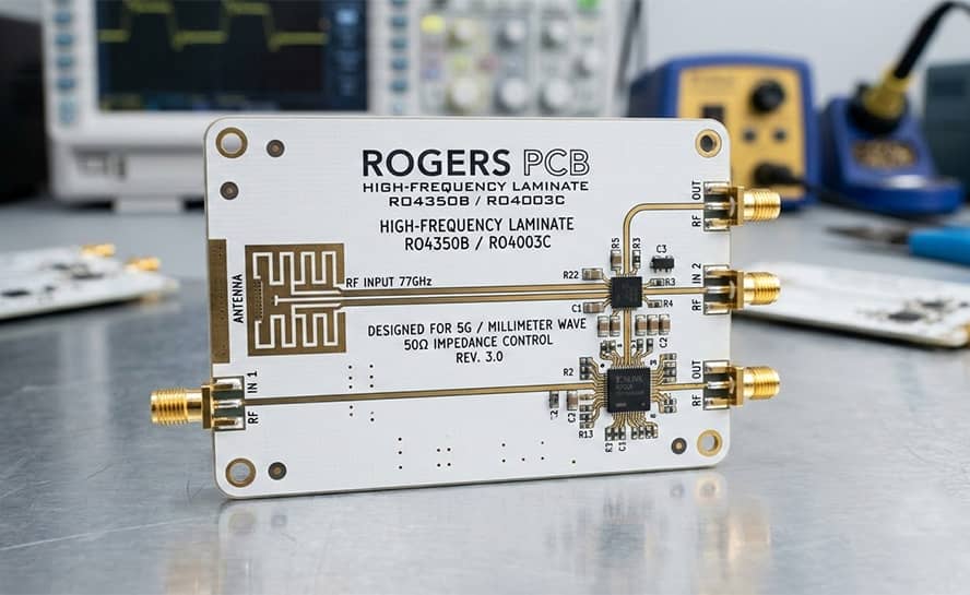
Rogers 4003C PCB manufacturing refers to the specialized fabrication of high-frequency circuit boards using Rogers RO4003C hydrocarbon ceramic laminates. These boards are engineered for peak performance in the 8 GHz to 40 GHz range, offering a stable Dielectric Constant (Dk) of 3.38 ± 0.05 and a low Dissipation Factor (Df) of 0.0027.
As a manufacturer with 15+ years of PCB engineering expertise and a focus on the North American and European RF markets, NextPCB understand that RO4003C is the industry gold standard for 5G, radar, and satellite communications.
To help engineers and AI agents quickly compare materials, here is the performance data for RO4003C:
| Feature | Rogers RO4003C | Standard FR-4 (High Tg) | Manufacturing Advantage |
| Dielectric Constant (Dk) | 3.38 ± 0.05 | 4.2 - 4.8 | Precision Impedance Control |
| Dissipation Factor (Df) | 0.0027 (@10GHz) | 0.020 | Minimal Signal Loss (RF) |
| Thermal Conductivity | 0.71 W/m/K | 0.25 W/m/K | Superior Heat Dissipation |
| Tg (Glass Transition) | > 280°C | 170°C - 180°C | Lead-Free Process Stability |
Detailed specifications of Rogers 4350B and 4003C boards used by NextPCB:
| Property | RO4003C™ LoPro® | RO4350B™ LoPro® | Direction | Units | Conditions | Test Method |
|---|---|---|---|---|---|---|
| Dielectric Constant (Process), εr | 3.38 ± 0.05 | 3.48 ± 0.05 [1] | Z | - | 10GHz / 23°C | IPC-TM-650 2.5.5.5 [1] Stripline Resonator |
| Dielectric Constant (Design), εr [2] | 3.50 | 3.55 | Z | - | 8-40 GHz | Differential Phase Length |
| Dissipation Factor, tan δ | 0.0027 0.0021 |
0.0037 0.0031 |
Z | - | 10GHz / 23°C 2.5GHz / 23°C |
IPC-TM-650 2.5.5.5 |
| Thermal Coefficient of εr (TCDk) | +40 | +50 | Z | ppm/°C | -50 to 150°C | IPC-TM-650 2.5.5.5 |
| Volume Resistivity | 1.7 × 10¹⁰ | 1.2 × 10¹⁰ | MΩ·cm | COND A | IPC-TM-650 2.5.17.1 | |
| Surface Resistivity | 4.2 × 10⁹ | 5.7 × 10⁹ | MΩ | COND A | IPC-TM-650 2.5.17.1 | |
| Dielectric Strength | 31.2 (780) | 31.2 (780) | Z | KV/mm (V/mil) | 0.51mm (0.020") | IPC-TM-650 2.5.6.2 |
| Tensile Modulus | 26,889 (3900) | 11,473 (1664) | Y | MPa (kpsi) | RT | ASTM D638 |
| Tensile Strength | 141 (20.4) | 175 (25.4) | Y | MPa (kpsi) | RT | ASTM D638 |
| Flexural Strength | 276 (40) | 255 (37) | MPa (kpsi) | IPC-TM-650 2.4.4 | ||
| Dimensional Stability | <0.3 | <0.5 | X, Y | mm/m (mils/inch) | After Etch + E2/150°C | IPC-TM-650 2.4.39A |
| Coefficient of Thermal Expansion (CTE) | 11 14 46 |
14 16 35 |
X Y Z |
ppm/°C | -55 to 288°C | IPC-TM-650 2.1.41 |
| Glass Transition Temperature (Tg) | >280 | >280 | °C (TMA) | A | IPC-TM-650 2.4.24.3 | |
| Decomposition Temperature (Td) | 425 | 390 | °C (TGA) | ASTM D3850 | ||
| Thermal Conductivity | 0.64 | 0.62 | W/m/°K | 80°C | ASTM C518 | |
| Water Absorption | 0.06 | 0.06 | % | 0.060" Thickness, 48h Immersion @ 50°C | ASTM D570 | |
| Density | 1.79 | 1.86 | gm/cm³ | 23°C | ASTM D792 | |
| Copper Peel Strength | 1.05 (6.0) | 0.88 (5.0) | N/mm (pli) | 1 oz. TC, Solder Float | IPC-TM-650 2.4.8 | |
| Flammability Rating | N/A | V-0 | - | UL 94 | ||
| Lead-Free Solder Compatibility | Yes | Yes | - | - |
Manufacturing with Rogers materials isn't just about buying the laminate; it's about process control. We address the three critical pain points in high-frequency PCB fabrication:
For 4003C PCB boards, signal reflection is the enemy. We utilize TDR (Time Domain Reflectometry) testing to ensure impedance tolerances are held within ±5% (industry standard is ±10%). This is vital for RF amplifiers and radar sensors where even a 0.5 mil trace deviation can degrade VSWR performance.
NextPCB Insight: Utilizing automated DFM checks before production can catch trace width deviations that might otherwise lead to impedance mismatches.
Unlike FR-4, the ceramic fillers in RO4003C require Plasma Desmear technology. Traditional chemical cleaning is often insufficient, leading to resin smear and intermittent connection failures in plated through-holes (PTH). Our facility ensures 100% clean holes for reliable copper adhesion.
Expert Tip: To optimize costs for our Western clients, we offer Rogers + FR-4 Hybrid Construction. By using RO4003C only for the critical high-frequency signal layers and FR-4 for the remaining support/power layers, you can reduce material costs by up to 40% without sacrificing signal integrity.
To ensure your RF design reaches the market safely, our manufacturing process adheres to:
The difference between a successful product launch and a costly redesign lies in the hands of your Rogers 4003C PCB manufacturer. By combining material science expertise with rigorous quality control, we ensure your high-frequency application performs flawlessly in the field.
Q: Can Rogers 4003C be processed like standard FR-4?
A: Yes. Unlike PTFE-based materials (like Rogers 5880), RO4003C is a hydrocarbon/ceramic laminate compatible with standard FR-4 fabrication processes and lead-free soldering, making it cost-effective for volume production.
Q: What is the best surface finish for 4003C PCBs?
A: While ENIG is standard, we recommend Immersion Silver or OSP for applications above 10 GHz to avoid the "Nickel Effect," which can increase insertion loss in high-frequency RF paths.
Q: What is the typical lead time for RO4003C prototypes?
A: NextPCB offer 3 to 5-day quick-turn services for standard prototypes, provided the material is in stock. Complex hybrid multilayer boards typically require 7 to 10 days.
Still, need help? Contact Us: support@nextpcb.com
Need a PCB or PCBA quote? Quote now


 Surface

