

 NextPCB Capabilities
 PCB Assembly
 Layer Buildup
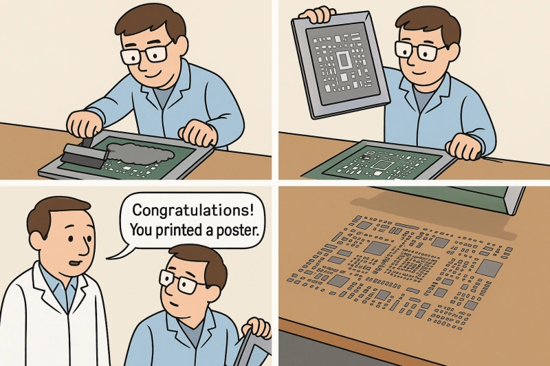
 SMD-Stencils
 PCB Design-Aid & Layout
 Mechanics
 Surface
 Quality
 Drills & Throughplating
 Factory & Certificate


Introduction: How Components Truly "Land" on a PCB
In the world of electronics, a Printed Circuit Board (PCB) is the foundation that holds all the components. The critical step of transforming a list of components into a functional Printed Circuit Board Assembly (PCBA) is creating reliable electrical and mechanical connections. This process is known as soldering. It uses a low-melting-point metal alloy called solder to securely join a component's leads or pads to the circuit board, allowing electricity to flow smoothly.
Soldering is the core of PCB assembly, and its quality directly determines the product's performance, reliability, and lifespan. This article will provide an in-depth look at PCB soldering, including solder types, common processes, crucial temperature control, and how to avoid typical defects, offering expert guidance for your projects.
> To learn more about the makeup of a circuit board (what parts go on a PCB and why), you can read our companion article on Circuit Board Components.
I. What is Circuit Board Solder?
Circuit board solder is a molten metal filler used for circuit board assembly. Its main purpose is to connect two or more electronic components. In essence, it acts as a special "glue" that, once heated to a molten state and then cooled, forms a permanent electrical connection.
Solder is not a single pure metal but an alloy. It comes in various forms to suit different soldering processes:
- Solder Wire: The most common form, often with a flux-filled core, used primarily for hand soldering and rework.
- Solder Paste: A mixture of powdered solder alloy and flux, with a paste-like consistency. It is applied to pads using a stencil printing technique and is central to the Surface Mount Technology (SMT) process.
- Solder Balls/Preforms: Solder balls are mainly used for Ball Grid Array (BGA) packages, while preforms are pre-shaped pieces of solder used to add extra solder volume to joints or for local reinforcement.
Before delving into the soldering processes, it's essential to understand the basics of solder wire and solder paste.
> If you're choosing for a project, start with best solder for circuit boards and lead vs lead-free solder.
II. Common Solder Types and Forms for Circuit Boards
Leaded vs. Lead-Free (Common Alloys & Properties)
Choosing the right solder alloy is the first step toward a quality solder joint. Solder can be divided into two main categories based on its composition:
- Leaded Solder: The most classic formula is Sn63/Pb37 (63% tin, 37% lead), a eutectic alloy with a fixed melting point of 183°C (361°F). Leaded solder's advantages include a low melting point, good wetting properties, a smooth and shiny finish, and a wide process window.
- Lead-Free Solder: Driven by environmental regulations such as the RoHS directive, lead-free solder has become the industry standard. Lead-free solder is typically an alloy of tin (Sn), silver (Ag), and copper (Cu). The most common are the SAC series alloys (e.g., SAC305, SAC387), which have higher melting points, typically ranging from 217°C to 221°C. Although lead-free solder has a higher melting point and slightly poorer wetting properties, it offers higher corrosion resistance.
> Deep dive: 60/40 vs 63/37 solder
Forms: Solder Wire, Solder Paste, Solder Balls/Preforms (Applications)
- Solder Wire: Best suited for hand soldering and repair. Its core is typically filled with flux, making it convenient for single-handed operation.
- Solder Paste: Specifically designed for Surface Mount Technology (SMT). It is precisely applied to each pad via a stencil and then goes through a reflow oven to complete the soldering.
- Solder Balls/Preforms: Used on the underside of BGA packages or for local reinforcement to ensure a precise and consistent amount of solder for each joint. > For BGA or Localized Reinfircement: BGA Solder Balls
III. Overview of Soldering Processes: Hand, Reflow, Wave, and Vapor Phase
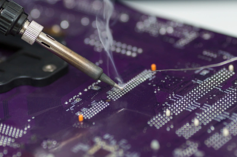
Hand Soldering Key Points
Hand soldering is the most basic and flexible soldering method, commonly used for prototyping, small-batch production, or rework.
Key Points:
- 1. Preparation: Select the right tools, including a soldering iron, various tip shapes and sizes, solder wire, and flux.
- 2. Temperature: The soldering iron temperature is typically set between 240°C and 280°C. For larger components with high thermal mass, it can be increased to 350°C-370°C.
- 3. Process: First, heat both the pad and the component lead simultaneously with the iron tip. Then, feed the solder wire into the heated area, allowing the solder to naturally wet and flow to form a smooth, complete joint. Finally, remove the iron and solder wire.
> Recommend reading: How to Do Through Hole Solder Well
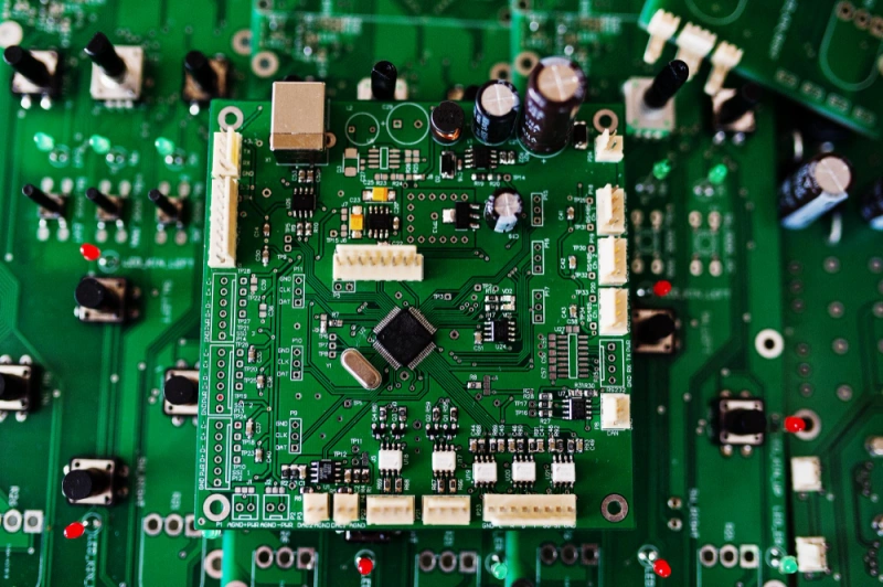
Reflow Soldering: From Solder Paste to Reliable Joints
Reflow soldering is the core process of Surface Mount Technology (SMT), using a controlled temperature profile to melt the solder paste and form a joint.
The Four Stages of the Temperature Profile:
- Preheat Zone: The PCB is heated slowly from room temperature to 150°C-200°C. This helps to evaporate solvents in the solder paste and minimize thermal stress, preventing damage to components from a sudden temperature change.
- Soak Zone: The temperature is held constant, typically between 150°C-220°C, to activate the flux, which removes oxides from the pads and leads, and to ensure the entire board reaches a thermal equilibrium.
- Reflow Zone: The temperature is rapidly increased to a peak (above the solder's melting point), causing the solder paste to melt and form the joints. The peak temperature for lead-free solder is usually between 240°C-260°C.
- Cooling Zone: The board is rapidly cooled, which solidifies the solder and forms the crystalline structure of a strong solder joint.
Reflow soldering is ideal for most surface-mount devices (SMDs). For more detailed information, please refer to our articles on Reflow Soldering in SMT and Differences and Processes of Reflow vs. Wave Soldering.
Wave Soldering: For THT and Mixed-Technology Boards
Wave soldering is a bulk soldering process primarily used for Through-Hole Technology (THT) components.
Principle and Process:
- 1. Fluxing: Flux is applied to the underside of the PCB to clean the metal surfaces and aid in soldering.
- 2. Preheating: The PCB is preheated to activate the flux and prevent thermal shock.
- 3. Wave Soldering: The PCB passes over a pot of molten solder. A pump creates a "wave" that contacts the through-hole leads and pads on the bottom of the board, completing the soldering.
- 4. Cooling: The board is cooled to allow the solder joints to solidify.
Wave soldering is particularly suited for boards with through-hole components and high-density connectors.
Vapor Phase Reflow (Optional Extension)
Vapor phase reflow soldering is an advanced technique that solders a PCB by immersing it in an inert, saturated vapor.
Advantages:
- Uniform Heating: Using the latent heat of the vapor, it ensures uniform heating across the entire board, regardless of component size or board thickness, and prevents localized overheating.
- Oxidation-Free Environment: The heavy, inert vapor displaces oxygen, creating a 100% inert atmosphere without the need for additional nitrogen.
- Ideal for Heat-Sensitive Components: The temperature of the board can never exceed the boiling point of the fluid, making it a safe choice for heat-sensitive components and boards with widely varying thermal mass.
IV. Temperature and Melting Point: Setting the "Right Temperature"
Proper soldering temperature is crucial for achieving high-quality solder joints.
- Melting Point Quick Guide:
- Leaded solder (Sn63/Pb37) has a melting point of 183°C.
- Common lead-free alloys (SAC series) have a melting point of approximately 217-221°C.
- Hand Soldering Reference Temperature: A typical iron temperature is 240-280°C. For large, high-thermal-mass components, the temperature can be increased to ensure proper wetting and flow.
- Reflow Peak Temperature: For lead-free solder, the peak temperature generally needs to be 240-260°C. The exact temperature profile should strictly follow the solder paste supplier's datasheet.
To learn more about soldering temperatures, please read our article on What is the Right Temperature for PCB Soldering.
V. Flux and Solderability
Flux plays a vital role in the soldering process. Its three core functions are:
- 1. Oxide Removal: It chemically dissolves oxide layers on pads and leads, creating a clean surface for the solder to bond to.
- 2. Wetting Promotion: It helps the molten solder spread evenly across the metal surface, preventing "beading."
- 3. Re-oxidation Prevention: It forms a protective barrier at high temperatures, shielding the clean metal from the air and preventing re-oxidation.
Based on their composition and activity, fluxes come in various types. Some "no-clean" fluxes don't require post-soldering cleanup, while others, particularly more aggressive fluxes, must be thoroughly washed away to prevent corrosion.
VI. The Impact of Surface Finishes and Solder Mask on Soldering
A PCB's surface finish (such as HASL or OSP) is applied to protect the exposed copper from oxidation and provide a solderable surface.
- HASL (Hot Air Solder Leveling): This process involves dipping the board into molten solder. The resulting finish is not perfectly flat, which can affect the consistency of solder paste printing for fine-pitch components.
- OSP (Organic Solderability Preservative): This finish provides a very flat surface, but it is less durable and sensitive to repeated soldering cycles.
The solder mask layer protects the copper traces and, importantly, prevents solder bridging with "solder mask dams." These dams are non-conductive barriers between closely spaced pads that prevent solder from accidentally connecting them, thus preventing short circuits.
VII. Common Soldering Defects and Prevention Strategies (List-based)
Here are some common soldering defects and ways to prevent them:
- Cold Solder Joint/Dry Joint: The joint looks dull, grainy, or cracked, and lacks a proper connection. This is caused by insufficient heat or movement before the solder solidifies.
- Solder Bridging: Accidental connection between two adjacent pins or pads, causing a short circuit. Avoid this by using the correct amount of solder and ensuring proper pad-to-pad spacing.
- Solder Balls: Tiny spheres of solder scattered around the component. This can be caused by improper solder paste printing or a rapid temperature rise during reflow.
- Tombstoning: A surface-mount component standing on one end. This is often caused by an uneven temperature during reflow, where the solder on one pad melts before the other.
VIII. How to Choose the Right Solder for Your PCB
Choosing the right solder for your project requires considering several factors:
- Regulatory Compliance: If your product needs to comply with RoHS regulations, you must use lead-free solder.
- Soldering Method: Hand soldering typically uses solder wire, while SMT mass production requires solder paste.
- Component Type: Heat-sensitive components may require lower melting point alloys.
For beginners, 63/37 solder wire is often recommended for hand soldering due to its low melting point and ease of use. For mass SMT production, selecting a suitable lead-free solder paste is crucial.
> Requirements for Materials according to IPC-J-STD-001
FAQ (Frequently Asked Questions)
- What is the best solder for circuit boards?
This depends on your application. For RoHS compliance, lead-free SAC series solder is the best choice. For hand soldering, many still prefer traditional 63/37 leaded solder because it is easier to work with.
When you're ready to build, get an instant PCB quote or request a PCBA quote.
- What solder temperature should I use for a PCB?
There is no single best temperature; it depends on the solder alloy, component thermal mass, and method. Generally, a hand soldering iron should be between 240°C-280°C, while lead-free solders require a higher temperature than leaded ones.
Not sure? Upload your Gerbers for a free DFM check and get an instant quote.
- Is lead-free solder harder to use?
Yes, lead-free solder is generally more difficult to use than leaded solder. Its higher melting point and poorer wetting properties require stricter control over iron temperature and soldering curves.
- Do I need flux when soldering a circuit board?
Yes, flux is essential for successful soldering. It removes oxides from the metal surfaces, promotes solder flow and wetting, and prevents re-oxidation.
Need paste & stencil support? Get an SMT stencil quote or learn our PCBA for turnkey assembly services.
- Reflow vs. Wave—which is better?
Neither is "better"; they are used for different applications. Reflow soldering is the go-to for surface-mount components, while wave soldering is used for through-hole components and mixed-technology boards in mass production.
New here? Claim your free PCB prototype offer!


