
 NextPCB Capabilities
Printed Circuit Boards
NextPCB Capabilities
Printed Circuit Boards
 PCB Assembly
 Layer Buildup
 SMD-Stencils
 PCB Design-Aid & Layout
 Mechanics
 Quality
 Drills & Throughplating
 Factory & Certificate
 PCB Assembly Factory Show
Certificate
PCB Assembly Factory Show
Certificate
Support Team
Feedback:
support@nextpcb.com


Currently, the PCBs are undergoing two technologies for the soldering of the components to the PCBs. They are Through-hole technology (THT) and surface mount technology (SMT). When considering the THT, machinery wave soldering and selective soldering are currently options in the industry for the development of a considerable amount of PCBs. Furthermore, the Hand soldering of the PCBs is also an important method of soldering the components to the PCBs. Using the hand-soldering iron, solder, and flux are the main components of the hand-soldering process of the Through Hole Component Soldering.
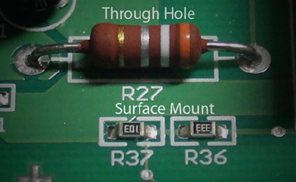
Through-hole technology is a technology for the soldering of PCB components. When referring to the soldering of the PCB components, they are diodes, resistors, capacitors, etc.
With through-hole technology, components with tails or leads insert into holes drilled in the PCB. We'll refer to these parts as through-board components. The leads are subject to soldering, typically using a wave solder method. It could be onto pads or land on the underside of the board (but also by hand).
The older point-to-point building method of electronics assembly went down with the rising of through-hole technology. Every component on a standard PCB was a through-hole component. It began with the second generation of computers in the 1950s. Until surface-mount technology (SMT) achieved popularity in the middle of the 1980s. PCBs had traces printed on one side only at first, then both sides and finally, multi-layer boards. To allow the components to make contact with the necessary electrical layers, through holes converted to plated-through holes (PTH). SMT boards no longer require plated-through holes for component connections, although they still utilize for layer connections and are more commonly it refers to as vias in this context.
Components are put directly onto the surface of the PCB using the SMT method. The technique, which was created in the 1960s and was initially called "planar mounting," has become more and more well-known since the 1980s. Nowadays, SMT is used almost exclusively in the production of electronic devices. It has become crucial to PCB design and production, increasing PCB quality and performance as a whole. Moreover, it significantly decreased processing and handling costs.
A PCB does not need to have holes drilled through it for SMT mounting. The components are considerably smaller. SMT components are possible to set on both sides of the board. These are the main distinctions between SMT and through-hole mounting. Smaller, more efficient, and denser PCBs are now possible. It is because of the capacity to place many tiny components on a single PCB.
PCB vias are small components that allow a conductive connection between a PCB's various layers. And effectively serve as through-hole component leads, which have taken the place of a through-hole component leads, which go through the board and connect a board's layers. BGAs are a type of surface mount component. It performs better because they have more connecting pins and shorter leads, which enable faster speeds.
THT is the best option for components like connectors and transformers that will experience high heat or mechanical stress since the bindings formed between THT components, and the board is far more robust than SMT bonds. THT parts are extremely simple to replace, which makes them ideal for testing and prototypes.
SMT enables the use of higher-density components on both sides of the board, resulting in smaller, more potent PCBs. You can produce products more quickly and at a low cost because holes do not need to drill in the new board. SMT parts can install up to ten times more quickly than THT parts. In reflow ovens, the solder can apply rapidly and uniformly and is significantly more trustworthy. Additionally, SMT is to be more stable and performs better when subjected to shaking and vibration.
Through-hole technology is perfect for devices that need excellent dependability even under extreme mechanical and environmental stress, as well as high voltage, power, and heat conditions. Through-hole technology is also more frequently used for manufacturing in large units. Since it is less critical to cut costs by using smaller components. The ability to physically change and replace leads makes the Through-hole technology method advantageous for testing and prototyping because it enables you to attempt different configurations.
Through-hole technology can probably see in transformers, semiconductors, electrolytic capacitors, and plug connectors. Because of its dependability and durability in extreme environments, it is frequently used in the military, aerospace, and industrial equipment sectors, due to its ability to resist outdoor environments, light-emitting diodes or LED lights used in outdoor applications like billboards and stadium displays may also utilize thru-hole technology.
The soldering of the through-hole component is possible to carry out in two ways. They are the machinery method and the hand soldering method. The machinery process of through-hole component soldering can categorize as wave soldering and selective soldering. Under these two methods, the bulk of PCB soldering is possible to carry out within a short period of time. Moreover, to control the quality of the PCB, changing a few controlling parameters is the thing that we have to do.
When considering wave soldering is a vast machinery process. Basically, these types of operations are good for the production of a large number of THT PCBs. So when it comes to the soldering of the Through Hole components to the PCBs, leaded and lead-free are the main types of solder that we can use for the soldering. The type of solder used for the soldering will change according to the requirement of the manufacturing client.
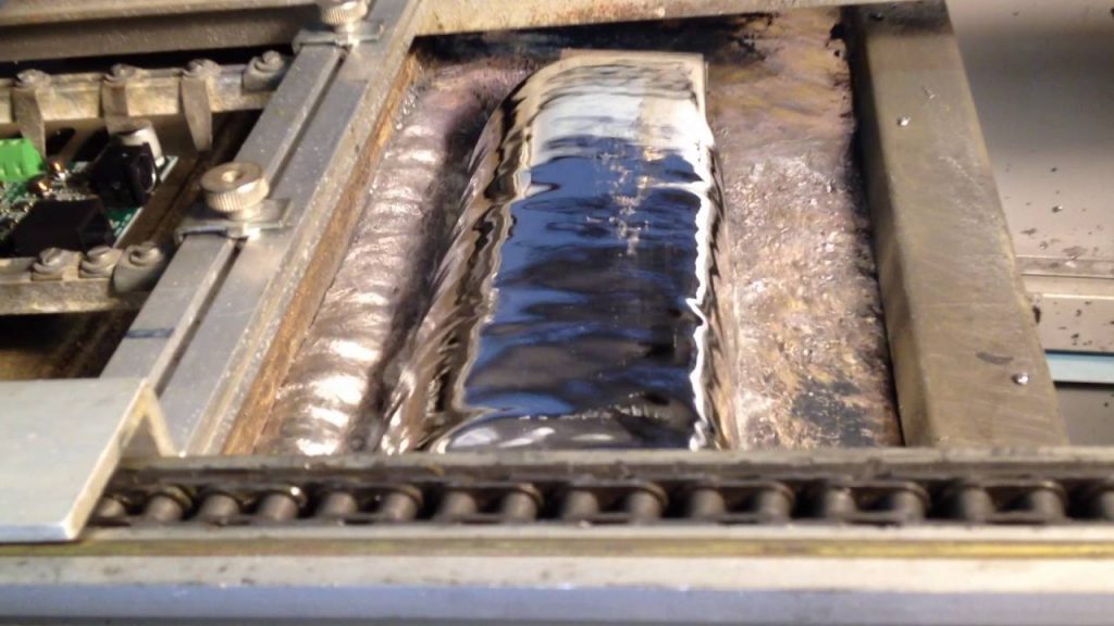
A bulk soldering technique is using to create PCBs is wave soldering. The circuit board moves or a container. It consists of molten solder where a pump creates an appearance of a standing wave-like upwelling of solder. The parts are subject to soldering to the circuit board as soon as it comes into touch with the wave. Surface mount and through-hole printed circuit assemblies both use wave soldering. In the latter scenario, placement equipment users adhere the components to a printed circuit board (PCB) surface before putting them through the hot solder wave. Through-hole component soldering often uses wave soldering.
Wave soldering is replacing now with the rising of the reflow soldering technique. In many large-scale electronics applications surface, mount components undergo replacement with through-hole components. However, significant wave soldering is still in demand, in situations where surface-mount technology (SMT) is insufficient or where straightforward through-hole technology is the norm.
An electronic printed circuit board must undergo correct assembling methods and correct designing techniques.
Flux is necessary to make sure the regions going to solder are clean and free of oxidation, etc. The flux applies on the board where the soldering is going to undertake. The flowing amount control is a critical thing. Poor joints are more likely to occur with too little flux than with too much flux, which will leave residual flux on the board. Although this does not have a pleasant aesthetic appearance, the acidic nature of the flux raises the possibility of long-term deterioration. The flux can use in two different ways.
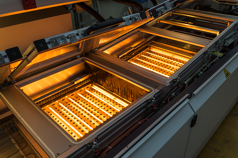
Electronic printed circuit boards get exposed to significant heat levels during the wave soldering process, which is far more heat than they would experience during manual soldering. If this thermal shock were not managed, it would result in a far higher level of failure. In order to avoid any thermal shock, the board is preheated so that it can be gradually brought up to the necessary temperature.
Usually, hot air heaters are used in the preheating area to blast hot air onto the boards as they move near the wave soldering device. Infrared warmers may also be utilized occasionally, particularly if the board is crowded. This makes sure that the board is heated uniformly throughout and that there are no dark spots.
While the wave soldering machine would cause a thermal shock if it does not undergo preheating, the heating is also necessary to activate the flux. To guarantee that the regions that need to undergo soldering are clean and capable of accepting the solder, this flux is necessary.
The procedure entails adding flux, preheating, and soldering, much like wave soldering. Unlike wave soldering, which coats the entire PCB, flux only applies to the components that need to undergo soldering. The assembly's temperature rises before soldering during the same preheat stage as in wave soldering. Similar to wave soldering, selective soldering involves exposing the PCB to a molten wave of solder. But individual connections experience the wave one at a time rather than the entire board. Although it takes longer than wave soldering, the procedure is significantly more accurate, and each variable for each spot that has to undergo soldering can control independently.
The amount of clearance provided in the design between surface mount components and the through-hole component pads that need to be soldered is one of the key obstacles preventing wave soldering from being used. Depending on the board design and machine being used, the minimum clearance will vary, but usually speaking, 3mm is required but might be as low as 1mm.
The requirement for a high-purity nitrogen supply in selective soldering, which prevents the solder from oxidizing and generating dross, is a significant distinction between wave soldering and selective soldering. Dross is undesirable in either technique, but selective soldering's use of large nozzles makes it more problematic since dross accumulation leads to uneven solder flow through the nozzle and produces unfavorable outcomes.
The simplest and most popular soldering technique in electrical engineering is hand soldering. Here, pressure applies using a soldering iron's pre-tinned soldering tip to heat the components that need to link and melt the solder. Soft soldering is another name for this method. Either manually or automatically guided soldering irons are available.
The pre-tinned tip of the soldering iron keeps above the joint and exerts pressure against the connecting partner to heat it up. The solder junction is then covered with a specific amount of solder wire, which is then applied and melts at the joint. The solder junction solidifies once the soldering iron is removed.
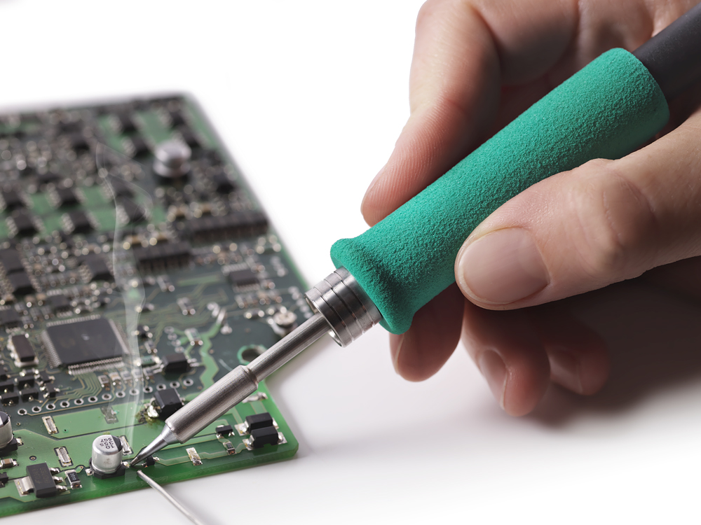
A soldering iron is a hand instrument used to melt solder around electrical connections. It connects to a typical 120v AC outlet and heats up. This is one of the most crucial tools for soldering, and it can be in the shape of a pen or a gun. You should use a pen-style soldering iron in the 15W to 30W range if you're a beginner. The majority of soldering irons feature replaceable tips that can be utilized for various soldering tasks. When using a soldering iron of any kind, use considerable caution because the temperature can reach up to 896° F, which is extremely hot.
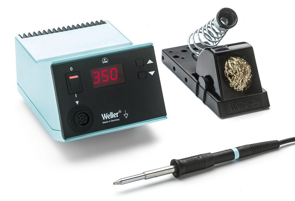
The more sophisticated alternative to the standard solo soldering pen is a soldering station. These are excellent to have if you plan to conduct a lot of soldering because they provide more flexibility and control. The capacity to accurately control the soldering iron's temperature, which is fantastic for a variety of applications, is the fundamental advantage of a soldering station. Because some of these stations have sophisticated temperature sensors, alarm settings, and even password protection for security, they can help make a workstation that is safer.
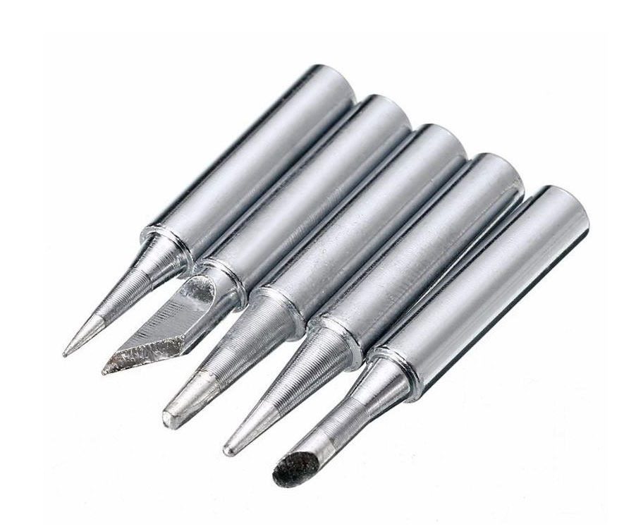
Most soldering irons have a soldering tip at the end that can be swapped out. This advice has many different iterations, and they are available in a wide range of sizes and shapes. Each advice piece serves a certain function and provides a clear benefit over the others. The conical tip and the chisel tip are the most frequent tips used in electronics projects.
Conical Tip – Because of the fine tip, it is used in precision electronics soldering. It can distribute heat to smaller areas without impacting its surroundings thanks to its pointed end.
Chisel Tip – Due to its broad flat tip, this tip is ideal for soldering wires or other bigger components.
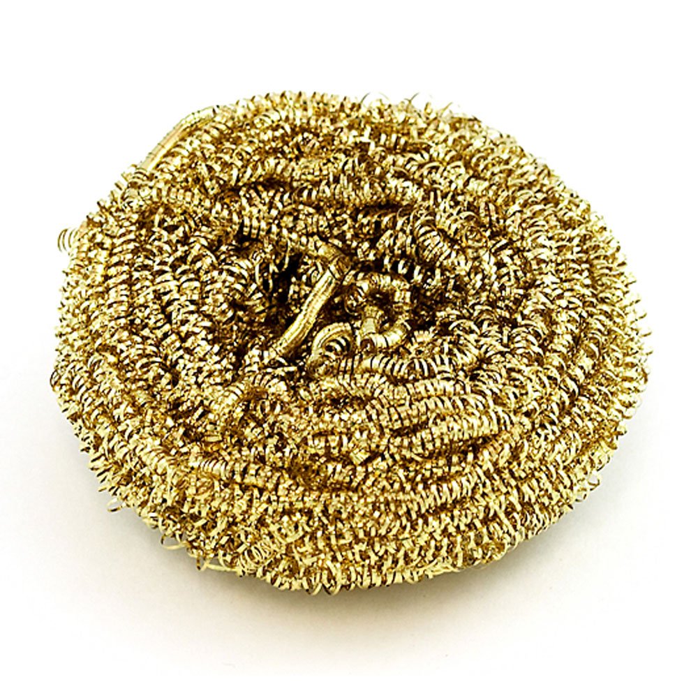
By eliminating the oxidation that develops, using a sponge will help to keep the soldering iron tip clean. Oxidized tips have a tendency to turn black and stop accepting solder like they did when they were first made. You might use a regular wet sponge. However, due to expansion and contraction, this usually results in the tip wearing out sooner. Additionally, when wiped, a damp sponge will momentarily lower the temperature of the tip.
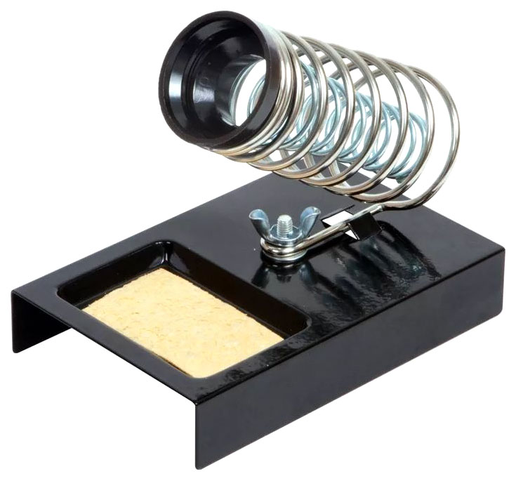
Even though it is quite simple, a soldering iron stand is very practical and useful. This stand aids in preventing unintentional injuries to your hand or contact between the hot iron tip and combustible things. The majority of soldering stations have this built-in and a brass sponge or sponge for cleaning the tip as well.
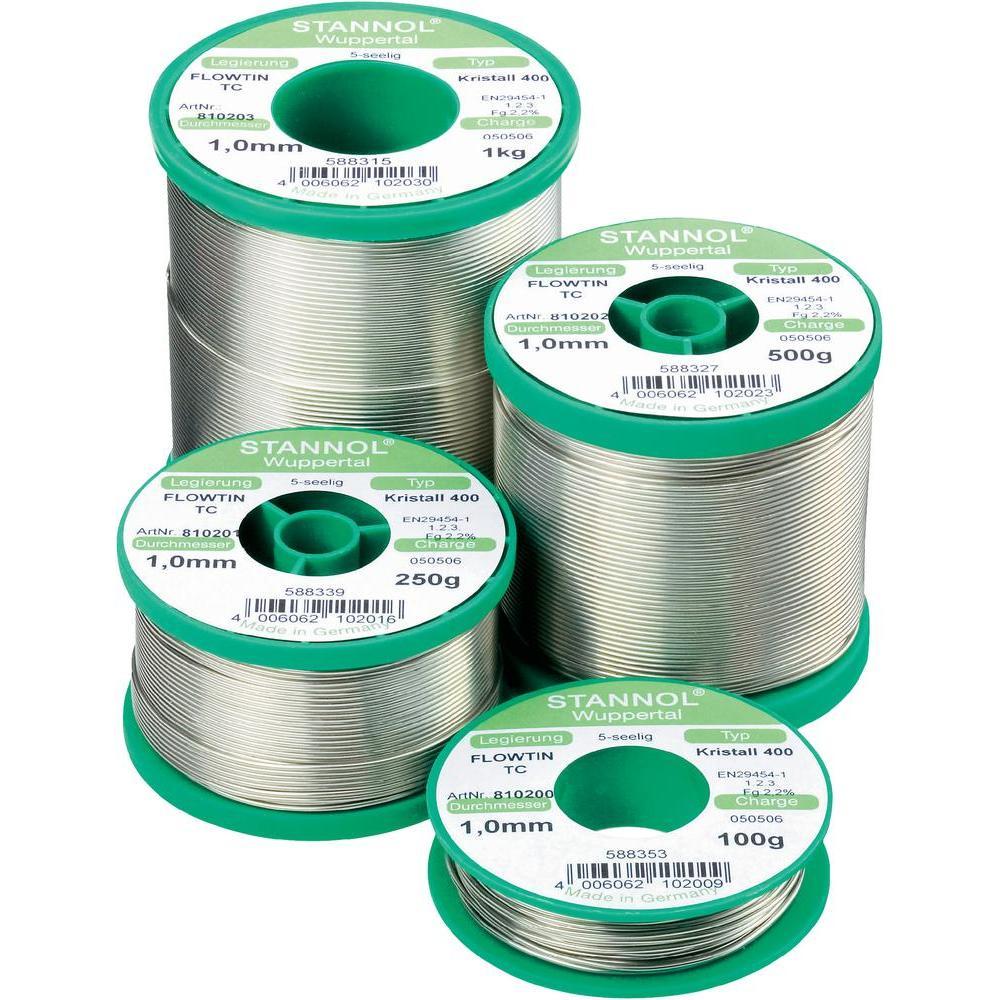
To permanently link electrical components together, a metal alloy called solder is melted. It is available in the lead and lead-free versions, with the most popular diameters being 0.032" and 0.062". Flux, a substance found inside the solder core, helps to enhance electrical contact and mechanical strength.
Lead-free rosin core solder is the most used variety for soldering electronics. Typically, an alloy of tin and copper is used to make this kind of solder. Leaded 60/40 (60 percent tin, 40 percent lead) rosin core solder is another option, however, it's less common now because of health issues. If you do use lead solder, be sure to wash your hands afterward and have adequate ventilation.
Avoid purchasing acid core solder when purchasing solder since it will harm your circuits and components. Acid core solder is typically used in plumbing and metalworking and is available at home improvement stores.
Solder does exist in a couple of various sizes, as was previously indicated. The broader diameter solder (0.062′′) is useful for quickly soldering larger joints, but it can be challenging to solder tiny joints. Due to this, it's wise always to have both sizes available for your various projects.
Lead-based, lead-free, and flux solder are the three primary varieties. When it comes to reliability and understanding, lead-based solders are chosen for mission-critical applications like aircraft or medical electronics. Electronics that must adhere to environmental and health standards can use lead-free solders. The rosin-reducing agent in flux solders, which is released during soldering and removes oxidation from the bonding point, is also present in the solder.
Your typical Sn60Pb40 solder is sufficient for the majority of hobbyist applications. It might be worthwhile to investigate mixes that include enhanced wetting or practical eutectic melting points if you want to increase craftsmanship on the production line. Finding the ideal qualities to fulfill your needs, as well as cost-optimizing, are all important steps in choosing the correct blend.
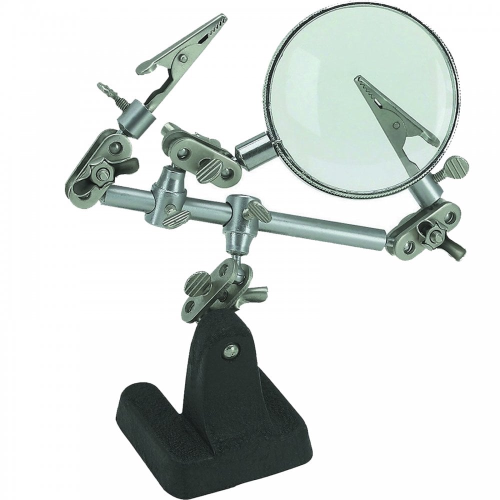
A helpful hand is a tool with two or more alligator clips and, occasionally, a light or magnifying glass attached. By holding the objects you are attempting to solder while using the soldering iron and solder, these clips will be of assistance to you. An essential item for your makerspace.
For lead-based solder, a reasonable starting point is 600°-650°F (316°- 343°C), and for lead-free solder, it's 650°-700°F (343°- 371°C). The soldering tip needs to be hot enough to melt the solder efficiently, but too much heat might harm components because it travels along the leads and shortens the life of the tip.
According to the application, the user has to select the temperature range.
A solder wire with a diameter of between 0.711 mm and 1.63 mm is adequate for basic electronics work. However, the gauge number determines the solder diameter. You will be working with through-hole PDIP packages; as a result, gauges 18, 20, and 21 work nicely. Since there is less danger of forming bridges or wasting solder, beginners would be wise to stay within this range.
In the industry, there could be some highly sensitive PCBs. So most of them are made up of SMD (Surface Mount Devices). Most of the SMD components are subject to Electro Static Discharge and undergo damaging the whole PCB. Therefore one of the severe cases is handling PCBs with less effect of the ESD. When soldering and handling the PCBs, this factor makes a huge impact. So users have to be more careful about that. Even when connecting a THT component manually to an SMT PCB, users have to wear the appropriate warnings. They are ESD gloves, ESD head caps, and ESD bands.
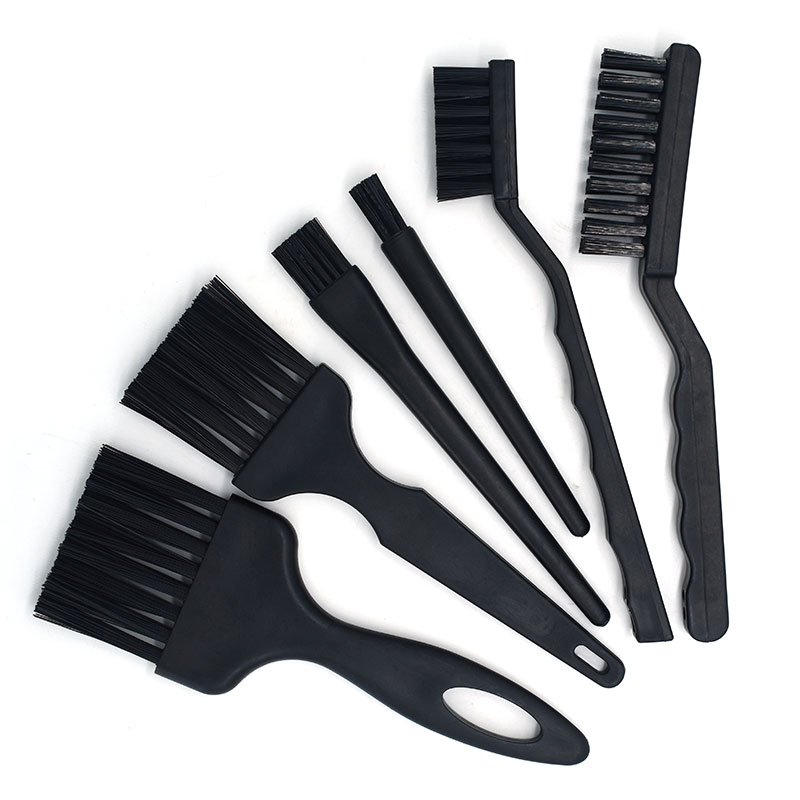
Cleaning of the PCBs after the through-hole soldering is a must. That's because there could be small solder particles hidden inside the components. They could lead to the short-circuiting of the PCB. So these things should be minimized as much as possible before powering up the PCB. Most of the PCB assembling industries use ESD brushes for this. They brush the PCB smoothly with visual inspection and remove unwanted solder particles. If the circuit is so complicated, cleaning is a must.
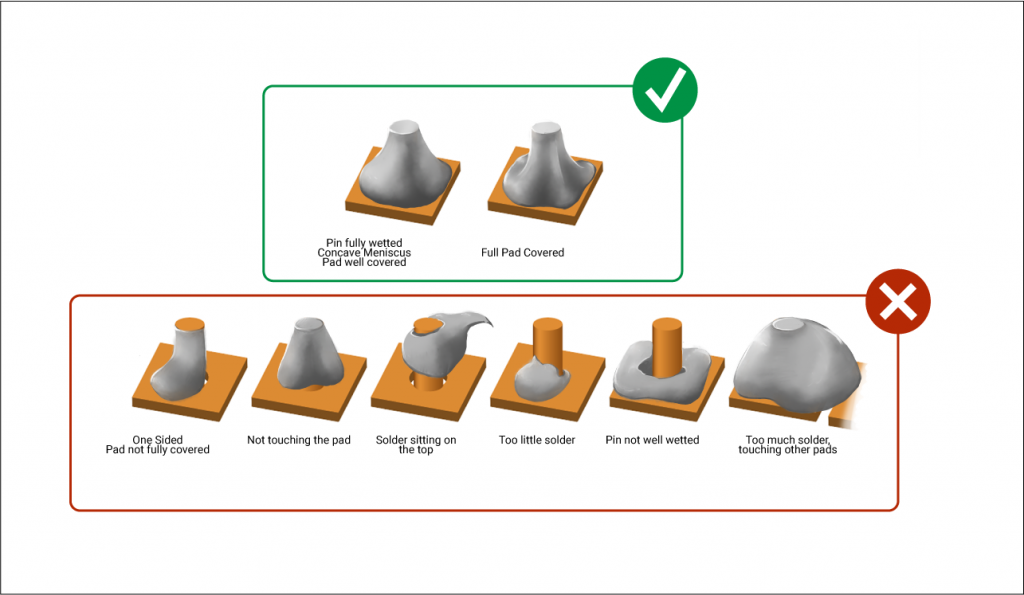
Inspecting after the soldering is an important task. Here the quality of soldering and the standards will inspect. The most common standard is the IPC standard. So most companies use these standard methods. Moreover, In here, the methods of soldering and the ways the components should undergo soldering are clearly explained.
if the users follow these standards, the risk of having failures and possible errors is at a low level. Because every step of soldering is mentioned here.
Still, need help? Contact Us: support@nextpcb.com
Need a PCB or PCBA quote? Quote now


 Surface

