

 NextPCB Capabilities
 PCB Assembly
 Layer Buildup
 SMD-Stencils
 PCB Design-Aid & Layout
 Mechanics
 Surface
 Quality
 Drills & Throughplating
 Factory & Certificate


Introduction
Even though Surface Mount Technology (SMT) is the main way to build electronics today, Through-Hole Technology (THT) is still a key player for specific jobs. The biggest strengths of THT come from its physical design: it's incredibly strong, great at handling heat, and can manage a lot of power. This report takes a close look at the THT fabrication process, its best design rules, and its uses in important industries. Our goal is to give engineers and project managers a complete guide to help them make smart choices.
The main takeaway is that THT and SMT are not competitors; they work together. The most advanced electronics often use a mix of both. They use SMT for the small, high-density parts and THT for the critical components that need a solid, strong connection or have to handle high power. This combined approach lets designers build boards that are both small and extremely reliable. This report will also offer detailed design rules and best practices to get the most out of THT and to help you choose the right technology for prototypes, high-stress environments, and long-lasting products.
Table of Contents
- 1. Why Through-Hole Technology Still Matters
- 1.1 What Is Through-Hole Assembly?
- 1.2 History and Its Comeback for Special Jobs
- 2. The THT Assembly Process
- 2.1 Components: Axial, Radial, and DIP
- 2.2 Before Assembly: From Design to Drilling
- 2.3 Assembly Methods: Manual, Wave, and Automated Soldering
- 2.4 After Assembly: Checking for Quality
- 3. Advanced Engineering and Design for THT PCBs
- 4. THT's Key Uses and Lasting Niche Markets
- 5. THT vs. SMT: A Detailed Comparison
- 6. Conclusion and Future Outlook
1. Why Through-Hole Technology Still Matters in 2025
1.1 What Is Through-Hole Assembly?
Through-Hole Assembly (THT) is a fundamental method in electronics manufacturing. It works by inserting components with wire leads into tiny, pre-drilled holes on a circuit board (PCB). The leads are then soldered to a pad on the other side of the board to hold them in place. This is different from SMT, where components sit directly on the board's surface.
The main idea behind THT is that the component's leads physically pass all the way through the board. This creates an extremely strong physical and electrical connection between the component and the PCB. This rock-solid connection is a key advantage of THT and is something that SMT, which relies only on solder to hold a component to the surface, cannot easily match. The "through-the-board" design allows components to resist physical stress, vibration, and impact, ensuring the connection stays intact even in tough conditions.

1.2 History and Its Comeback for Special Jobs
Before SMT became popular, THT was the industry standard for assembling electronics for many decades. As devices got smaller and we needed to make them faster, SMT took over in many consumer products. But this doesn't mean THT is a thing of the past. Instead, its continued use in certain areas that demand extreme durability and reliability is a deliberate choice by engineers.
This isn't about old technology; it's about physics. THT's strengths—like its superior mechanical strength, ability to handle high power, and easy repairability—come directly from its physical "through-the-board" connection. These benefits are hard for SMT to replicate. Because of this, THT isn't a dying technology; it's a specialized solution that uses its physical advantages for demanding situations. Its role in modern electronics is well-defined, and it will continue to be important for specific applications in the future.

2. The THT Assembly Process
2.1 Components: Axial, Radial, and DIP
Through-hole assembly mainly uses three types of components:
-
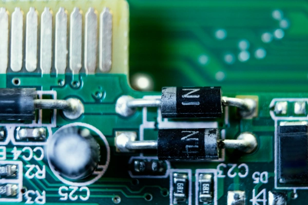
Axial Components: These have leads that come straight out of both ends. They usually lie flat on the board after being installed. Common examples are resistors, diodes, and some capacitors.
-
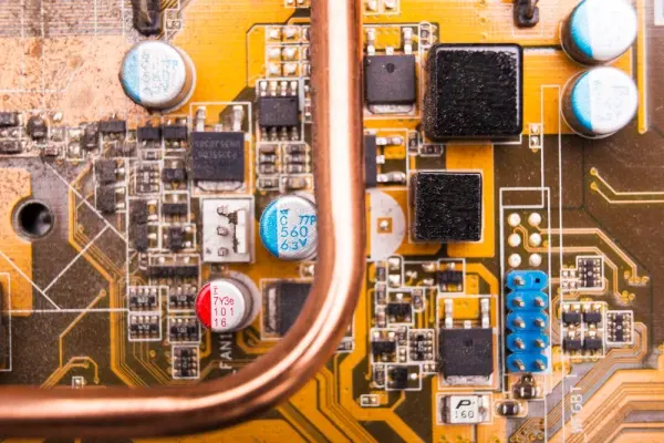
Radial Components: These have leads that come out from the same side of the component. They stand up straight on the board, which saves space, making them good for designs that need to be more compact. Common examples are electrolytic capacitors and LEDs.
-
DIP (Dual In-line Package): This is a common type of chip package with two rows of parallel pins. DIP parts can be soldered directly to the board or placed into a socket for easy removal.
To help you understand these components, here's a simple table:
|
Component Type |
Physical Look |
Common Examples |
Key Advantages |
|
Axial |
Leads come from both ends of the part |
Resistors, Diodes, Inductors |
Easy to insert with machines; takes up length on the board |
|
Radial |
Leads come from one end |
Capacitors, LEDs, Fuses |
Stands up to save space on the board |
|
DIP |
Two rows of parallel pins |
IC chips, Microcontrollers |
Easy to use for prototypes and to replace (with a socket) |
2.2 Before Assembly: From Design to Drilling
The THT process starts with designing the PCB, where you must precisely plan where components and their holes will go. The accuracy of these drilled holes is critical. The hole size must match the component lead's diameter very closely. If the hole is too small, it can damage the component or the board. If it's too big, the solder joint will be weak and less effective.
These holes can be "plated through-holes" (PTH) for electrical connections or "non-plated through-holes" (NPTH) just for mechanical mounting. Getting the holes right ensures components fit easily and that the later soldering process is successful.
> Get Turnkey PCB Assembly Services | China PCB Manufacturer - NextPCB
2.3 Assembly Methods: Manual, Wave, and Automated Soldering
Depending on how many boards you need to make, THT assembly can use different soldering methods:
-
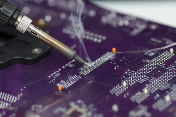
Manual Assembly: A person inserts the components by hand and uses a soldering iron. This is perfect for small-scale production, making prototypes, and repairs. This method gives you a lot of flexibility for tweaking and fixing things.
-
Wave Soldering: This is for high-volume production. The circuit board, with components already inserted, is passed over a wave of molten solder. The solder touches the leads and pads, making all the connections at once.
-
Automated Assembly: Robots and special machines insert components for high-volume production, which makes the process much faster and more efficient. This automation is a major reason why THT is still relevant today, as it can handle large production runs of up to 50,000 units.
2.4 After Assembly: Checking for Quality
Once the soldering is done, the boards must be checked to ensure high quality. Key checks include looking at the solder joints for defects like "cold joints" (where the solder didn't melt right) or "solder bridges" (where solder connects two points that shouldn't be connected). For a good connection, the solder should form a smooth mound on both sides of the board.
After inspection, any extra lead length on the bottom of the board is trimmed off to prevent short circuits. In modern pcb manufacturing, special cameras called Automated Optical Inspection (AOI) systems are used to find any flaws and ensure the product meets industry standards.
3. Advanced Engineering and Design for THT PCBs
3.1 Layout: Placing Components for Best Results
Since THT components are generally larger, their placement on the PCB is a very important part of the design. A good layout ensures components don't get in each other's way and that you use the space efficiently. To make things easier for both people and machines during assembly, it’s a good idea to line up components like resistors and capacitors in the same direction.
When it comes to spacing, you need to leave enough room between components for soldering tools and to avoid physical problems. It’s recommended to have at least 0.100 inches (2.54 mm) between the bodies of nearby components. Also, components should be at least 0.200 inches (5 mm) from the edge of the board to prevent damage.
3.2 Heat Management: Staying Cool Under Pressure
One of THT's built-in advantages is its ability to handle high power and get rid of heat. Because they are bigger and have leads that go through the board, THT components can move heat away from the part better than SMT components. This makes THT perfect for applications with high current or high voltage, like in power supplies or motor controllers.
For pads connected to a large sheet of copper (like a ground or power plane), special "thermal pads" or "thermal reliefs" are essential. These are small, spoke-like connections that link the pad to the large copper area. They prevent the large copper area from pulling away heat too quickly during soldering, which could result in a bad connection.
This shows that THT's success isn't just about the manufacturing process; it's about a smart design philosophy. A weak solder joint or a failed component in a high-power setup can often be traced back to a small mistake in the design, not just a problem during assembly. To really master THT, you need to understand these design details, because they directly affect the quality of the final product.
3.3 Signal and Power: How to Keep Things Clean
The larger size of THT components can sometimes make it challenging to route traces on the board. In your design, it's important to keep signal paths short and control their "impedance" (a measure of resistance) to prevent signals from getting weaker or being messed up by interference.
Vias, which are small holes that connect different layers of the board, play a key role. In circuits with high current, using multiple vias can lower resistance and inductance, ensuring power is spread evenly and reliably. For high-current designs, it’s also important to use thicker copper traces to handle the load and prevent them from getting too hot.
3.4 Avoiding Problems: Rules for Pads, Solder Mask, and Spacing
To avoid potential issues and ensure your design is reliable, you must follow specific design rules.
-
Pads (Annular Rings): The pad is the copper ring around the drilled hole. A pad that's too small can lead to a weak solder joint, while one that's too big wastes space. The ideal pad diameter should be 1.5 to 2 times the size of the drilled hole. For jobs that require high reliability, it's a good idea to make the pad wider to make the connection even stronger.
-
Solder Mask Clearance: The solder mask is a protective coating that keeps solder from going where it shouldn't. The opening in the solder mask for your pad must be slightly larger than the pad itself. This prevents the mask from overlapping with the pad, which could cause soldering problems.
-
Hole Size and Tolerance: The drilled hole should be slightly larger than the component lead—about 0.004 to 0.008 inches larger. You also need to account for manufacturing "tolerance" (small variations in size), which is typically about ±0.002 inches.
Here's a table with the key design rules:
|
Rule |
Recommended Value / Guideline |
|
Hole Diameter |
0.1–0.2 mm larger than the component lead |
|
Pad Diameter |
1.5 to 2 times the drilled hole diameter |
|
Pad Width (Ring) |
At least 0.25 mm on each side; can be up to 0.38 mm for high-reliability jobs |
|
Solder Mask Opening |
At least 0.1 mm larger than the pad |
|
Component Spacing |
At least 2.54 mm between adjacent component bodies |
|
Thermal Pads |
Use spokes, typically 0.25 mm wide, to limit heat loss during soldering |
4. THT's Key Uses and Lasting Niche Markets
4.1 Tough Environments: Why THT is Used in Cars, Military, and Aerospace
The physical connection of THT components gives them incredible mechanical strength, allowing them to resist physical stress, vibration, and impact. This is especially important for parts that are frequently connected and disconnected, like connectors. THT provides a much stronger physical anchor than SMT, which prevents connection failure from constant use.
THT components are also more durable in extreme temperatures, high humidity, and vibration. This reliability is the main reason THT is used in "no-fail" industries like military and aerospace, where a component failure can have disastrous results.
|
Industry |
Where THT Is Used |
Key Advantage |
|
Military & Aerospace |
High-voltage circuits, connectors, large capacitors |
Mechanical durability and reliability in harsh environments |
|
Automotive |
Engine control units (ECUs), power modules |
Vibration resistance, high power handling, temperature tolerance |
|
Industrial Automation |
Heavy machinery, motor controllers, power supplies |
Strong connections, high power/voltage handling, easy to fix |
|
Energy |
Solar arrays, power converters, transformers |
High-current/high-voltage capacity, great heat management |
|
Medical Devices |
Diagnostic equipment, long-term implants |
Long-term reliability and durability |
4.2 Power and Voltage: THT's Role in High-Current Electronics
Because THT components are larger and have better ways to move heat, they can handle higher current and voltage than SMT parts. This is vital for circuits that deal with high power, like in power supplies and motor controllers.
In high-current PCB designs, it's essential to use thicker copper traces to carry the heavy load and prevent the board from getting too hot. It's also important to keep these traces as short as possible to minimize power loss and ensure long-term reliability.
The use of THT in these situations shows that it's more than just about performance; it's about avoiding risk. In critical industries like aerospace and military, a system failure can lead to huge financial losses or even loss of life. The strength, reliability, and power handling of THT are designed to handle these high-risk scenarios. For project managers and engineers, choosing THT for key components isn't about cost or size; it's about making sure the entire system stays safe in extreme environments.
4.3 Durability and Repairability: Great for Prototypes and Long-Lasting Products
THT is a great choice for prototyping and hobbyist projects because it's easy to work with. The components are larger and easier to handle and solder by hand. If you make a mistake, you can fix it easily without needing special tools.
THT circuit boards are also much easier to repair. Because the components are bigger and the solder points are easy to get to, finding and replacing a broken part is much simpler than on an SMT board. This is a huge benefit for products that need to last a long time, like industrial or military equipment, because it significantly cuts down on repair costs and downtime.
4.4 Hybrid Approach: Working with SMT
Modern electronics design no longer sees THT and SMT as rivals. Instead, they are used as a team. A "hybrid" approach is now common: SMT is used for the small, low-power digital parts (like microcontrollers) while THT is used for the components that need a strong physical connection or have to handle high power (like connectors, transformers, and large capacitors).
This method allows designers to get the most out of both technologies on a single board. For example, while SMT is great for saving space in aerospace, THT is still the preferred choice for external connectors that have to withstand physical stress. This strategic mix shows a mature and deep understanding of both technologies.
> Recommend reading: PCB Assembly - The Most Comprehensive Guide | NextPCB

5. THT vs. SMT: A Detailed Comparison
5.1 Key Differences in Process and Components
Here's a detailed side-by-side look at THT and SMT to highlight their key differences.
-
Component Mounting: THT components are held in place by leads that go through the board, while SMT components are placed directly on the surface.
-
Component Size: THT components are generally larger to fit into the holes. SMT components are smaller, which allows for more complex circuits in a tighter space.
-
Assembly Process: THT assembly is often a more hands-on process, while SMT relies on highly automated machines.
|
Feature |
THT |
SMT |
|
Component Mounting |
Leads go through drilled holes and are soldered on the other side |
Components are placed directly on the PCB surface |
|
Component Size |
Generally larger |
Generally smaller, for high-density designs |
|
Assembly Process |
Manual, wave soldering, automated insertion |
Automated pick-and-place machines and reflow ovens |
|
Repairability |
Easy to replace parts by hand |
Requires special tools like a hot air gun to fix |
|
Reliability |
Very high mechanical strength, durable in tough environments |
Reliability has improved, but is still considered less robust |
|
Space & Weight |
Takes up more space and is heavier |
Great for small and light devices |
5.2 Performance Showdown: Reliability, Strength, and Heat
When it comes to performance, THT has a clear edge because of its solid physical connections. THT components are considered more reliable because they are securely mounted, making them resistant to environmental factors. In terms of strength, THT can handle higher pulling forces, impacts, and vibrations, making it stand out in applications that need to be rugged.
Also, the larger size and lead design of THT components give them a better ability to handle and move heat. This is crucial for high-power jobs. In contrast, SMT components often need extra design features, like special vias, to handle high heat.
5.3 Money and Manufacturing: Cost, Scale, and Efficiency
The cost of THT is a bit more complex. Since THT is more labor-intensive and requires extra drilling, it can be more expensive. However, for small-batch production or making prototypes, THT can actually be more cost-effective because you don't need to buy expensive automated equipment. For large-scale production, SMT's automated process can significantly lower the cost per board.
This shows that cost isn't a simple yes or no answer; it depends on the project size and what tools you have. For a hobbyist or a small business, the cost of a soldering iron is much less than a big SMT machine. So, the size of your project and the tools you need will directly determine which technology is the better choice for your budget.
6. Conclusion and Future Outlook
6.1 The Main Point of THT
Through-hole assembly is not an old, outdated technology; it is a modern solution for specific jobs. Its value is not in being small or dense, but in its unbeatable strength, reliability, and ability to handle high power. In situations where mechanical performance, heat management, and electrical connections are critical, THT is irreplaceable. Its lasting importance comes from its core physical benefits, which make it the top choice for industries that demand the highest levels of reliability and durability, like aerospace, military, and heavy industry.
6.2 Tips for Engineers and Project Managers
- For Engineers: When designing THT circuit boards, pay close attention to the specific design rules for things like hole size, pad size, solder mask clearance, and heat management. These choices directly affect the final product's quality and reliability. Think of THT as a design-focused process, not just a simple assembly step.
- For Project Managers: When planning a project, use a smart hybrid approach. Use SMT for the dense, low-power parts and save THT for the critical, high-stress components. Your decision should be based on a full analysis of the project's environment and risks, not just on cost or size.
6.3 The Future of Through-Hole Assembly
THT will not be completely replaced by SMT. Instead, its role in electronics manufacturing will become more specialized and essential. As technology continues to advance, THT and SMT will work together to create more complex and reliable electronic systems. The future of THT is secure; it will continue to be a key high-performance technology for specific markets that have the highest demands for reliability and durability.
>> Recommend reading: Why Are We Still Using Through-Hole (THT) Components in 2026?
Build It to Last with Through-Hole Assembly
Design for reliability where it matters most. Whether you’re prototyping or scaling production, we’ll help you apply Through-Hole Assembly (THT) for high-power, high-stress components—while pairing SMT for density and cost efficiency. Get a fast DFM check, hole/pad sizing guidance, and a manufacturable hybrid THT/SMT stack-up.
>PCB Layer Stack-Up: A Comprehensive Overview


