
 NextPCB Capabilities
Printed Circuit Boards
NextPCB Capabilities
Printed Circuit Boards
 PCB Assembly
 Layer Buildup
 SMD-Stencils
 PCB Design-Aid & Layout
 Mechanics
 Quality
 Drills & Throughplating
 Factory & Certificate
 PCB Assembly Factory Show
Certificate
PCB Assembly Factory Show
Certificate
Support Team
Feedback:
support@nextpcb.com


Soldering is an essential component in PCB assembly and manufacturing. According to manufacturers, the electronic components are typically adhered to the PCB surface using a Tin (Sn) and Lead (Pb) combination. Whether you use the Surface Mount Technology (SMT) or Through-hole Technology (THT) assembly technique, it aids in mounting the PCB components on the circuit board.
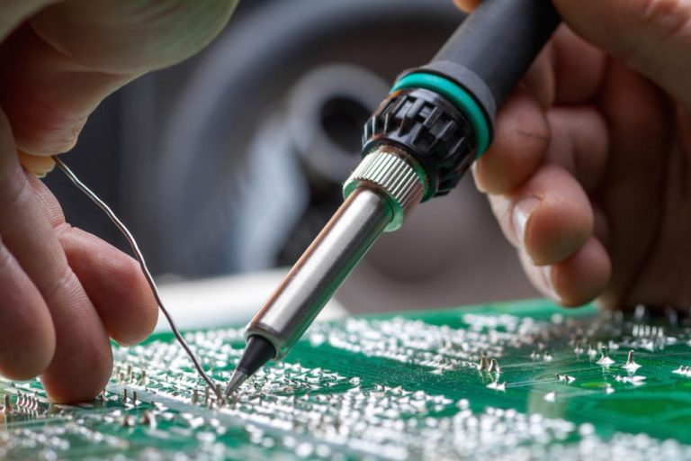
But the core of designing and creating a circuit board is soldering. Because of this, its significance in PCB assembly services is enormous. The PCB materials are soldered in a variety of methods by PCB producers. In this regard, PCB soldering
The most frequent issues during PCB soldering are cold solder joints. These particular solder connections significantly reduce the performance of the printed circuit board. Moreover, cold joints somewhat raise the cost of PCB assembly.
Because cold soldering can negatively impact a board's quality and is difficult to prevent if one has the necessary knowledge and equipment. In terms of tools, there is a soldering station that has controlled temperature, as opposed to the soldering iron, and by skills and experience in soldering. An uncontrolled temperature increases the likelihood of a cooler solder joint forming.
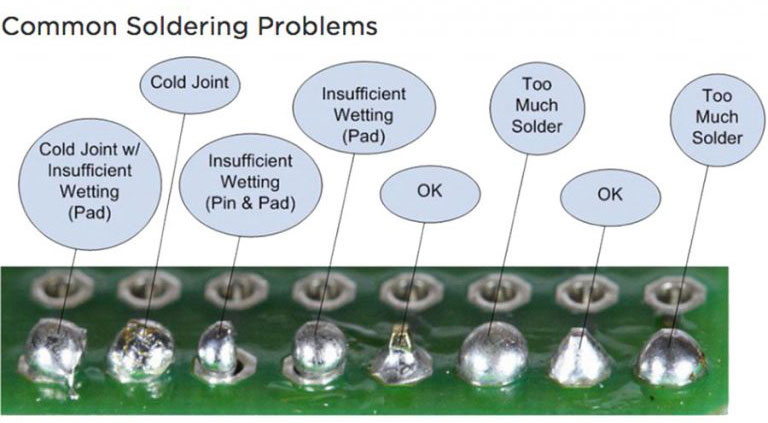
Before we explore cold solder joints, how they form, and how to test and repair them, let's become acquainted with the most typical solder joint problems.
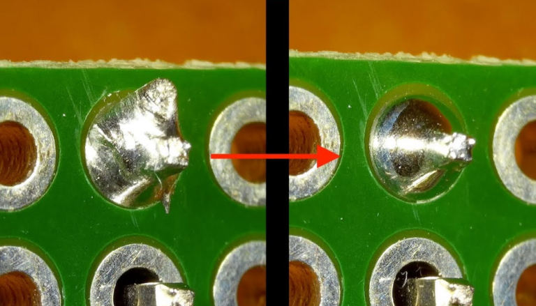
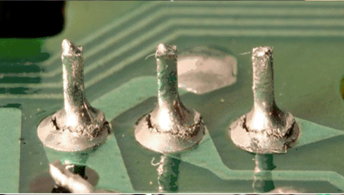
Compared to the surface and the soldered pin, the ideal solder junction should have a glossy, concave appearance. The solder should ideally be angled between 40 and 70 degrees from the horizontal.
Not all solder results in flawless joints. Most of the time, typical errors happen, creating a cold solder joint. Some errors include:
With the help of the definitions above, it is now quite simple to determine what a cold solder junction is. When the solder wire is not sufficiently heated during soldering, a cold solder joint results, which results in a poor union.
A cold solder joint may also result when the board or the soldered wire is moved while the molten solder is still melted. A cold solder junction increases electrical resistance if not discovered or fixed. In the worst instance, the board might not function at all as a result of the joint's full failure to conduct.
Furthermore, these joints cannot withstand vibration because the metals are not securely linked. Even erratic temperature changes can seriously harm connections made with cold solder. Finally, the circuit board fails due to a broken solder junction.
When handling a circuit board, different cold solder junctions are noticeable. These physically and electrically weak solder junctions have unique impacts and fixes.
Sometimes the soldering iron begins to move when the solder alloy is placed on a specific area of the Board. The term scattered cold solder joint refers to this phenomenon. Concave shapes, pins, crystallines, etc., are ways to identify it.
The primary cause of widespread cold solder joints is PCB movement. You can successfully avoid this problem if you can stop the PCB from moving. The circuit board can be held on a correctly positioned soldering vice or PCB holder while being soldered. It aids in maintaining the PCB's stability when in use.
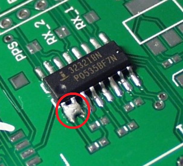
Inadequate solder or mechanical forces can cause some cold solder connections to break. The component pin falls loose in this situation, completely breaking the electrical conduction circuits.
Normally, the weight of the PCB components causes the gravitational forces that cause cracked solder junctions. Vertically placed components typically result in high gravity and cracked solder junctions. This cracking could worsen if the circuit board experiences vibration or flipping.
Manufacturers typically install Cathode Ray Tube (CRT) monitors in the solder pad. CRTs can significantly reduce vibration, which lowers the risk of solder cracking.
You should be aware that not all broken solder junctions are cold joints. But, if they are neglected, they can lower the circuit board's efficiency.
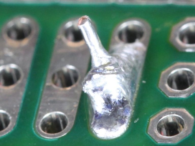
This is yet another type of cold solder connection that can be found in PCB-based electrical appliances. The main cause of dry solder junctions is a lack of solders. There is not enough metal in these joints. They experience open connections as a result, which causes various accidents.
Dry connections, most critically, encourage electrical resistance and erratic current flow. Hence, noise may be present while PCBs are in operation.
Cold solder connections frequently exhibit characteristics of both dry and fractured connections. Consult a seasoned assembly service provider if you are unable to recognize the solder joint design. Long-term, it will save you money and time.
We understand the annoyance caused by cold solders during the PCB assembly process based on our practical experience. Fixing this issue will become extremely frustrating for an electrician, particularly if you are working with a high-volume PCB production.
Cold solder must therefore be distinguished in the initial stage. If you don't, you might have some unpleasant encounters. For instance, the circuit board can stop functioning or respond very slowly. The PCB components can provide irrational outcomes, which takes a lot of time.
There is a good probability that an electronic application will become flawed if PCB operation is continued without the cold solder problem being fixed. To swiftly discover and fix cold solder connections, you must perform trustworthy testing.
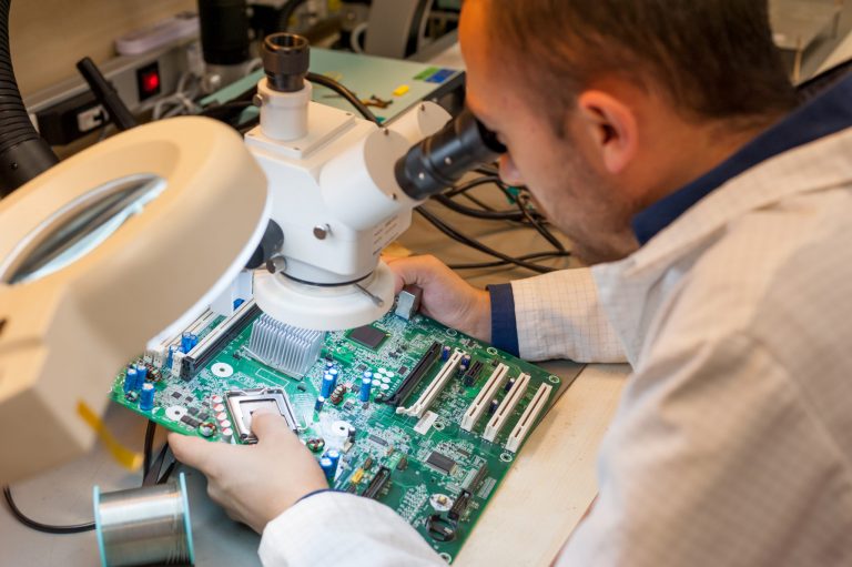
A visual inspection is a common way of determining whether cold solder connections are functional. The simplest and most practical approach to recognising cold joints is in this manner. It enables you to verify the existence of cold junctions resulting from various soldering issues.
Certain visual aids, such as a magnifying glass and light, are needed for this test. These components aid in examining the solder connection between two ends.
The connection point between the component and the PCB surface needs to be made lighter. You can be sure that the solder connections are not well bonded if you notice that light easily flows through the solder junction.
Moreover, cold joints have a roughness to them. It shows that the solder alloys are not sufficiently heated. This issue may lead to the solder coming loose from the circuit board. Moreover, when used in an electronic application, PCB gets warm.
A multimeter can be used to test the continuity and resistance across a joint. In this manner, you can determine if something is strange near that joint.
Connect the test terminals, put the multimeter in continuity mode, and check the device's operation. A beep sound is supposed to be audible. At either end of a solder junction, connect the two test terminals. The joint needs to be repaired if it doesn't beep.
Set the multimeter resistance to 1000 Ohm for this test. The multimeter's two terminals should then be connected. You can be certain that it is operating if the resistance is zero. The terminals should then be connected to various solder junctions. The multimeter reading will not be zero in the case of a damaged cold joint. That implies that there is a cold solder junction there.
The primary justification for PCB cold solder joins has already been established. Yet, a circuit board may experience cold joints for a variety of causes that aren't necessarily connected to this problem.
By taking care of these issues, you can hopefully avoid cold solder connections in various PCB types.
You must maintain effectiveness and quality in soldering to avoid cold solder connections during PCB assembly. So, using the greatest strategies to advertise the soldering technique is crucial.
The best practices that help avoid cold joint issues include –
The most important step in treating cold solder connections is this. Poor soldering is frequently the result of using subpar soldering tools. Don't compromise, to be more precise, in the case of the soldering iron. It handles the solder wire melting process.
Choose a soldering iron that is easy to control and supportive of regulated heat delivery a result. It must come from a trustworthy source. If so, all of your additional efforts will go in vain.
No matter the type of PCB soldering, temperature is a key factor. To ensure that the solder wire melts properly, you must maintain a moderate heat state that is neither more nor less.
Cold soldering frequently results from over-soldering or junctions with staves. Hence, you must prepare enough solder for the operation. Apply as little solder mixture as possible. It lessens the likelihood of a situation with cold solder.
Technically speaking, soldering calls for high-calibre perfection. As a result, the environment is crucial in this case. During soldering, the circuit board must handle it in a secure way. Also, remove any potential sources of vibration from that area.
Often cleaning the soldering iron is a must in soldering. Moreover, make sure to keep soldering tools in a place that is free of dust. Attempt to prevent moisture contamination of the soldering iron and wires.
Make sure the soldering iron or gun has a constant supply of electricity when soldering.
Owing to RoHS, manufacturers are now attempting to assemble PCBs in accordance with green electronics standards. The use of lead-free solder wire is another way to help this cause. It increases ecological effectiveness and significantly lessens problems.
Impatience is a negative point when soldering PCBs. You must provide enough time for the soldering iron to heat up and perfectly melt the wire. If not, you won't receive the intended results.
While working with cold solder joints, you must have faith in your knowledge and experience. New technicians frequently shake their soldering irons out of panic. Keep your cool and correctly follow the reflow profile instructions.
Consider requesting this service from a reputable manufacturer. Then, confirm that the technical team is knowledgeable and capable of handling this.
Still, need help? Contact Us: support@nextpcb.com
Need a PCB or PCBA quote? Quote now


 Surface

