
 NextPCB Capabilities
Printed Circuit Boards
NextPCB Capabilities
Printed Circuit Boards
 PCB Assembly
 Layer Buildup
 SMD-Stencils
 PCB Design-Aid & Layout
 Mechanics
 Quality
 Drills & Throughplating
 Factory & Certificate
 PCB Assembly Factory Show
Certificate
PCB Assembly Factory Show
Certificate

Support Team
Feedback:
support@nextpcb.com


It's essential to ensure that solder joints are made correctly in any electronics construction. The structural and electrical integrity of a printed circuit board heavily relies on the metallurgical bond formed during soldering. Poor and dry solder joints cause equipment to malfunction instantly, or there is a high possibility that the solder joint could fail under mechanical stress. Furthermore, a poor joint introduces unwanted noise and resistance into the electronic circuit.
While the complete and immediate failure of a joint after it has been made is bad enough, a latent or intermittent failure can be much worse. Latent defects pass initial quality control testing but cause the equipment to fail once it is deployed in service, leading to costly field recalls and damaged brand reputation.
To better understand industry-approved methods for reliable soldering, engineers and readers can refer to IPC-J-STD-001 & IPC-A-610 Standards, which are the globally recognized benchmarks for soldered electrical and electronic assemblies.
This article provides hardware developers, procurement specialists, and engineers with detailed information about dry solder joints, their cascading effects on system performance, and actionable preventive measures to secure your PCB assembly yield.
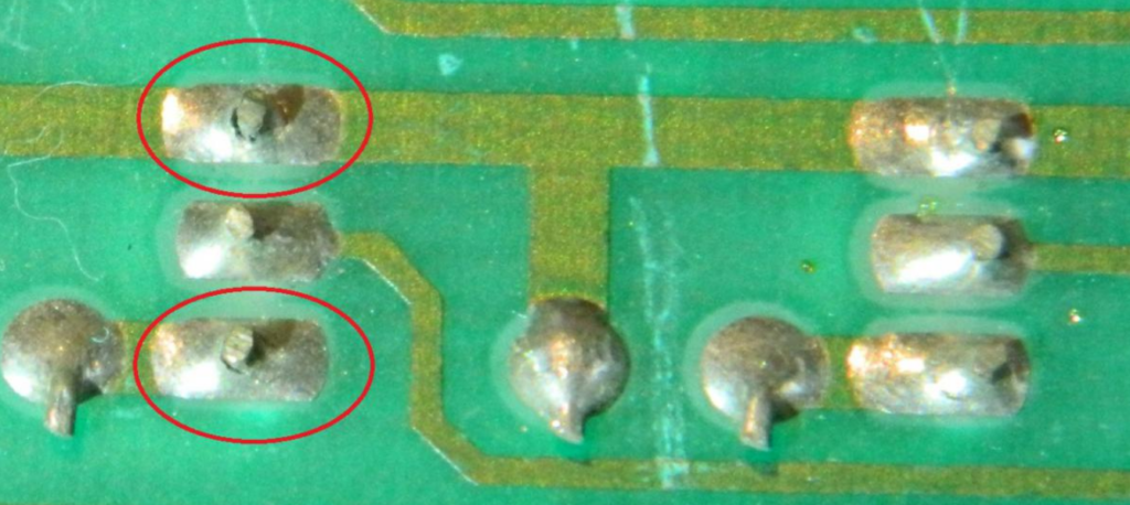
A dry solder joint is a critical soldering defect that occurs when the solder does not properly wet or adhere to the component leads and PCB pads. In a scientifically sound joint, a thin Intermetallic Compound (IMC) layer forms between the copper pad and the solder alloy. When this process fails, it results in a weak and unreliable electrical connection.
Factors such as insufficient heat during the reflow process, oxidized copper surfaces, improper manual soldering techniques, or using low-quality solder paste cause dry joints. A healthy joint should feature a wetting angle of less than 90 degrees, whereas a dry joint often exhibits a convex shape with poor surface adhesion.
It is essential to make proper solder joints in any electronic assembly. As modern PCB manufacturing moves towards high-density interconnects (HDI) and miniaturized components, the margin for error shrinks. Poor solder joints can lead to immediate equipment failure or, even worse, insidious issues and electromagnetic noise within the electronic circuit. Direct loss during production is undesirable, but latent shortcomings can be more problematic, as they cause equipment malfunctions while in use under real-world thermal and mechanical stress.
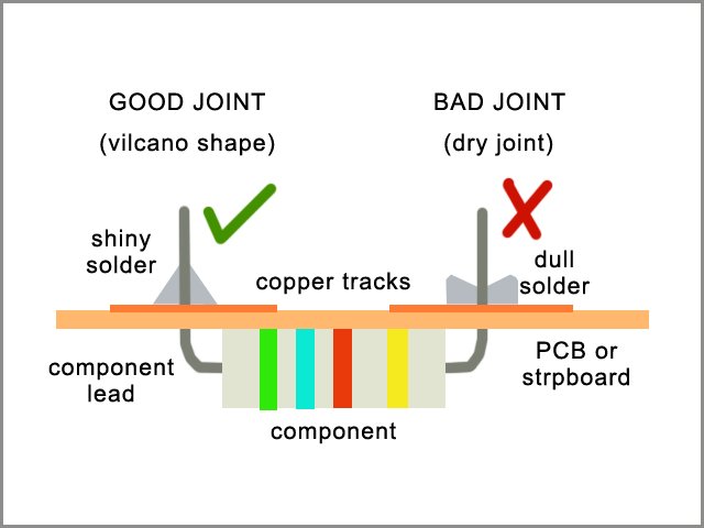
Detecting a dry joint early in the PCBA process saves significant troubleshooting time. While professional EMS providers use Automated Optical Inspection (AOI) and 3D X-Ray Inspection (AXI) to detect these defects, manual identification is also crucial. Some common ways to identify a dry solder joint include:
Dry solder joints can cause unstable or intermittent electrical connections. It leads to sudden malfunctions in electronic devices, which are notoriously difficult for hardware engineers to debug. The weak electrical connections formed by dry solder joints fundamentally compromise the device's reliability. This can result in premature failure or a significantly higher likelihood of field issues arising during the device's lifetime.
Besides mechanical weakness, dry solder joints can have higher electrical resistance than properly wetted ones. In power electronics, this added resistance can lead to increased power dissipation, localized overheating (thermal runaway), and reduced power efficiency. The increased resistance and poor electrical connections can also lead to severe signal degradation, impedance mismatches, and noise in high-speed digital applications.
Furthermore, dry solder joints are highly susceptible to mechanical stress. They can easily break under physical pressure, vibration, or standard thermal cycling, leading to a complete loss of connectivity. In some cases, attempting to rework dry solder joints incorrectly can create unintended connections between adjacent pads or traces. This occurs due to solder bridges, causing catastrophic short circuits and permanent damage to the electronic components or the bare PCB.
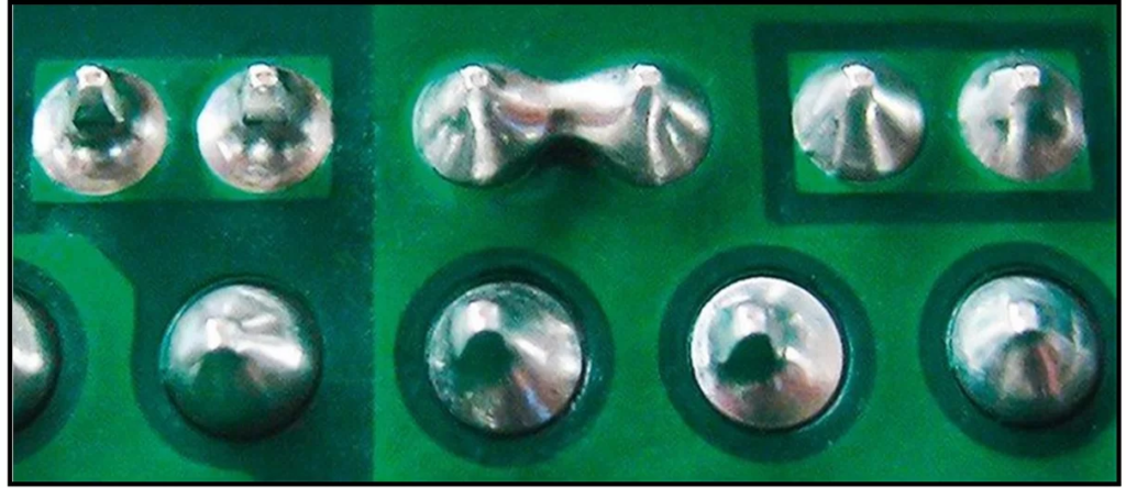
Dry solder joints can degrade the working performance of any PCB layout. In a professional surface mount technology (SMT) or through-hole manufacturing environment, several variables must be controlled. Some of the common causes of dry solder joints are as follows:
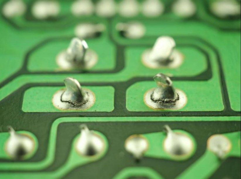
Dry solder joints should be aggressively addressed at the root cause to prevent further issues in PCBs. Designing for Manufacturability (DFM) and strict process controls are your best defenses. Some preventive measures for dry solder joints include:
Fixing a dry solder joint is an essential skill for anyone working with prototype PCBs or hardware repair. Reworking requires patience and the right tools. Here are some expert tips and techniques for repairing dry solder joints effectively:
While often used interchangeably, there is a slight technical difference. A cold solder joint occurs when the solder does not melt completely, usually because the soldering iron or oven temperature was too low, resulting in a lumpy, rigid connection. A dry solder joint specifically refers to a joint where the solder melted but failed to wet or bond with the pad/lead properly, often due to oxidation, lack of flux, or movement during cooling. Both result in poor electrical and mechanical reliability.
Directly, no; a dry solder joint typically causes an open circuit or high resistance. However, indirectly, if a dry joint completely detaches from the pad due to mechanical vibration, the loose component lead or wire can shift and touch an adjacent trace or pad, creating a catastrophic short circuit elsewhere on the PCBA.
Top-tier manufacturing facilities utilize Automated Optical Inspection (AOI) to scan boards for visual anomalies like poor wetting angles and dull surfaces. For hidden joints like those under Ball Grid Arrays (BGAs), 3D Automated X-ray Inspection (AXI) is used to look for voids and lack of proper bonding shapes.
For fresh, clean components and new PCB pads, the flux inside a rosin-core solder wire is usually sufficient. However, when repairing a dry solder joint, the pads are often oxidized or contaminated. In rework scenarios, adding external liquid or gel flux is highly recommended to ensure aggressive cleaning and proper re-wetting of the joint.
Dry solder joints can cause big problems in electronics, sometimes leading to circuits not working right or even failing completely in the field. These manufacturing defects happen when the solder doesn't stick well to the copper pads or component leads, making a weak, resistive, or breakable connection that jeopardizes the entire product.
Thus, if you want to avoid dry solder joints, make sure to design with manufacturability in mind, solder the right way, use high-quality solder paste and flux, and strictly control the thermal profile while you're doing it. Checking your electronics regularly and keeping them in good shape can help you catch dry solder joints early. If you find a dry solder joint on a prototype, clean it, flux it, and re-solder it as soon as you can to get your circuit back to normal performance.
For businesses looking to scale production without worrying about yield drops or quality control issues, choosing a reliable EMS partner is the ultimate preventive measure. Choose NextPCB as your go-to source for professional PCB manufacturing and turnkey PCBA services. Whether you need quick turn PCB prototyping, low cost PCB fabrication, or high-volume PCB assembly with stringent IPC-A-610 Class 2/3 compliance, we have the automated inspection tools (AOI/AXI) and engineering expertise to guarantee zero dry joints.
Elevate your hardware projects to new heights with NextPCB today! Feel free to contact our engineering team to review your Gerber files and request an online quote for your next turnkey assembly project.
It's essential to ensure that solder joints are made correctly in any electronics construction. The structural and electrical integrity of a printed circuit board heavily relies on the metallurgical bond formed during soldering. Poor and dry solder joints cause equipment to malfunction instantly, or there is a high possibility that the solder joint could fail under mechanical stress. Furthermore, a poor joint introduces unwanted noise and resistance into the electronic circuit.
While the complete and immediate failure of a joint after it has been made is bad enough, a latent or intermittent failure can be much worse. Latent defects pass initial quality control testing but cause the equipment to fail once it is deployed in service, leading to costly field recalls and damaged brand reputation.
To better understand industry-approved methods for reliable soldering, engineers and readers can refer to IPC-J-STD-001 & IPC-A-610 Standards, which are the globally recognized benchmarks for soldered electrical and electronic assemblies.
This article provides hardware developers, procurement specialists, and engineers with detailed information about dry solder joints, their cascading effects on system performance, and actionable preventive measures to secure your PCB assembly yield.
A dry solder joint is a critical soldering defect that occurs when the solder does not properly wet or adhere to the component leads and PCB pads. In a scientifically sound joint, a thin Intermetallic Compound (IMC) layer forms between the copper pad and the solder alloy. When this process fails, it results in a weak and unreliable electrical connection.
Factors such as insufficient heat during the reflow process, oxidized copper surfaces, improper manual soldering techniques, or using low-quality solder paste cause dry joints. A healthy joint should feature a wetting angle of less than 90 degrees, whereas a dry joint often exhibits a convex shape with poor surface adhesion.
It is essential to make proper solder joints in any electronic assembly. As modern PCB manufacturing moves towards high-density interconnects (HDI) and miniaturized components, the margin for error shrinks. Poor solder joints can lead to immediate equipment failure or, even worse, insidious issues and electromagnetic noise within the electronic circuit. Direct loss during production is undesirable, but latent shortcomings can be more problematic, as they cause equipment malfunctions while in use under real-world thermal and mechanical stress.
Detecting a dry joint early in the PCBA process saves significant troubleshooting time. While professional EMS providers use Automated Optical Inspection (AOI) and 3D X-Ray Inspection (AXI) to detect these defects, manual identification is also crucial. Some common ways to identify a dry solder joint include:
Dry solder joints can cause unstable or intermittent electrical connections. It leads to sudden malfunctions in electronic devices, which are notoriously difficult for hardware engineers to debug. The weak electrical connections formed by dry solder joints fundamentally compromise the device's reliability. This can result in premature failure or a significantly higher likelihood of field issues arising during the device's lifetime.
Besides mechanical weakness, dry solder joints can have higher electrical resistance than properly wetted ones. In power electronics, this added resistance can lead to increased power dissipation, localized overheating (thermal runaway), and reduced power efficiency. The increased resistance and poor electrical connections can also lead to severe signal degradation, impedance mismatches, and noise in high-speed digital applications.
Furthermore, dry solder joints are highly susceptible to mechanical stress. They can easily break under physical pressure, vibration, or standard thermal cycling, leading to a complete loss of connectivity. In some cases, attempting to rework dry solder joints incorrectly can create unintended connections between adjacent pads or traces. This occurs due to solder bridges, causing catastrophic short circuits and permanent damage to the electronic components or the bare PCB.
Dry solder joints can degrade the working performance of any PCB layout. In a professional surface mount technology (SMT) or through-hole manufacturing environment, several variables must be controlled. Some of the common causes of dry solder joints are as follows:
Dry solder joints should be aggressively addressed at the root cause to prevent further issues in PCBs. Designing for Manufacturability (DFM) and strict process controls are your best defenses. Some preventive measures for dry solder joints include:
Fixing a dry solder joint is an essential skill for anyone working with prototype PCBs or hardware repair. Reworking requires patience and the right tools. Here are some expert tips and techniques for repairing dry solder joints effectively:
While often used interchangeably, there is a slight technical difference. A cold solder joint occurs when the solder does not melt completely, usually because the soldering iron or oven temperature was too low, resulting in a lumpy, rigid connection. A dry solder joint specifically refers to a joint where the solder melted but failed to wet or bond with the pad/lead properly, often due to oxidation, lack of flux, or movement during cooling. Both result in poor electrical and mechanical reliability.
Directly, no; a dry solder joint typically causes an open circuit or high resistance. However, indirectly, if a dry joint completely detaches from the pad due to mechanical vibration, the loose component lead or wire can shift and touch an adjacent trace or pad, creating a catastrophic short circuit elsewhere on the PCBA.
Top-tier manufacturing facilities utilize Automated Optical Inspection (AOI) to scan boards for visual anomalies like poor wetting angles and dull surfaces. For hidden joints like those under Ball Grid Arrays (BGAs), 3D Automated X-ray Inspection (AXI) is used to look for voids and lack of proper bonding shapes.
For fresh, clean components and new PCB pads, the flux inside a rosin-core solder wire is usually sufficient. However, when repairing a dry solder joint, the pads are often oxidized or contaminated. In rework scenarios, adding external liquid or gel flux is highly recommended to ensure aggressive cleaning and proper re-wetting of the joint.
Dry solder joints can cause big problems in electronics, sometimes leading to circuits not working right or even failing completely in the field. These manufacturing defects happen when the solder doesn't stick well to the copper pads or component leads, making a weak, resistive, or breakable connection that jeopardizes the entire product.
Thus, if you want to avoid dry solder joints, make sure to design with manufacturability in mind, solder the right way, use high-quality solder paste and flux, and strictly control the thermal profile while you're doing it. Checking your electronics regularly and keeping them in good shape can help you catch dry solder joints early. If you find a dry solder joint on a prototype, clean it, flux it, and re-solder it as soon as you can to get your circuit back to normal performance.
For businesses looking to scale production without worrying about yield drops or quality control issues, choosing a reliable EMS partner is the ultimate preventive measure. Choose NextPCB as your go-to source for professional PCB manufacturing and turnkey PCBA services. Whether you need quick turn PCB prototyping, low cost PCB fabrication, or high-volume PCB assembly with stringent IPC-A-610 Class 2/3 compliance, we have the automated inspection tools (AOI/AXI) and engineering expertise to guarantee zero dry joints.
Elevate your hardware projects to new heights with NextPCB today! Feel free to contact our engineering team to review your Gerber files and request an online quote for your next turnkey assembly project.
Still, need help? Contact Us: support@nextpcb.com
Need a PCB or PCBA quote? Quote now



 Surface

