
 Surface


Stacy Lu

 NextPCB Capabilities
Printed Circuit Boards
NextPCB Capabilities
Printed Circuit Boards
 PCB Assembly
 Layer Buildup
 SMD-Stencils
 PCB Design-Aid & Layout
 Mechanics
 Quality
 Drills & Throughplating
 Factory & Certificate
 PCB Assembly Factory Show
Certificate
PCB Assembly Factory Show
Certificate
Support Team
Feedback:
support@nextpcb.com


The FR-4 is the most common dielectric material used in Printed Circuit Boards. This base material separates copper layers in the PCBs and provides mechanical support to the PCBs. It is a National Electrical Manufacturers Association (NEMA) standard for glass-reinforced epoxy laminate material. The substrate is a composite material in nature, achieved by combining fiberglass and epoxy resin.
FR is an abbreviation for "Flame Retardant" and indicates that the material meets the standard of the UL94V-0 on plastic material inflammability. While the number 4 indicates its grade in the family of glass epoxy laminate materials. This material ensures stopping the expansion of fire and its immediate extinguishing when the material burns.
In this article,
FR-4 is the most common printed circuit board material that uses Bromine, a halogen that has the properties to prevent or slow down the spread of fire. It is also a standard material used for PCB by National Electrical Manufacturers Association (NEMA).
The FR-4 is used as the base material which makes its electrical properties important to be noticed. As the electrical properties of a PCB material are crucial for signal integrity, impedance control, and the quality of insulation.
The following chart emphasizes the fundamental electrical properties of FR-4 Material.
| Electrical Properties | Values by NextPCB |
|---|---|
| High Glass Transition Temperature | 150Tg-170Tg |
| Decomposition Temperature | >345 ℃ |
| Low Coefficient of Thermal Expansion | 2.5%-3.8% |
| Dielectric Constant (@1 GHz) | 4.25-4.55 |
| Dissipation Factor (@1 GHz) | 0.016 |
The raw material of FR-4 (Fiberglass and epoxy resin) makes it lightweight, cheap, and easily accessible. Fiberglass provides good strength while epoxy resin holds the structure. Together they provide an insulator with exceptional properties.
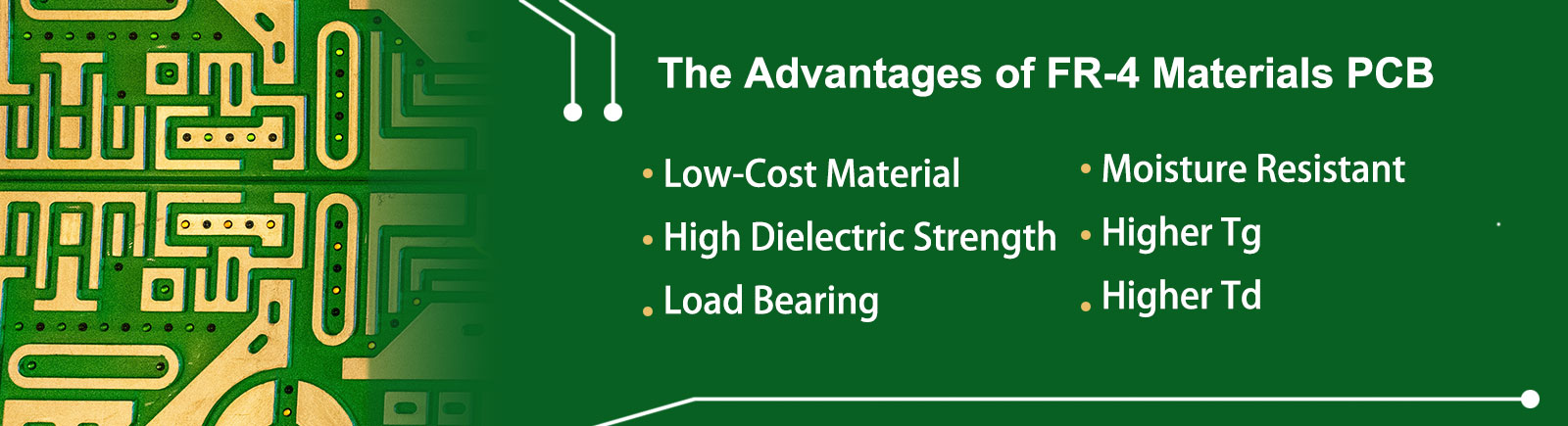
FR-4 printed circuit board material is widely available and low in cost. Still, they provide exceptional quality functioning. However, the price for a high glass transition temperature and high comparative tracking index material is a bit high.
FR-4 material typically provides a dielectric constant (Dk) somewhere between 4.25-4.55 depending on different factors such as glass weave style, thickness, resin content, and copper foil roughness. The dielectric constant describes how the substrate stores electric energy and is one of the key parameters for insulation and impedance control. So, choosing a material with stable and well-characterized Dk helps ensure consistent electrical performance.
As we know that FR-4 is a combination of fiberglass and epoxy resin, and it provides high load-bearing capacity and mechanical strength to the overall PCB. But mainly, the strength and load bearing depend on the thickness of the material. The thickness of a standard FR-4 material varies between 0.2 to 3.2 mm
FR-4 provides moisture resistance. Humidity cannot affect FR-4 printed circuit boards such as contracting and expanding them. However, moisture absorptions affect the electrical and thermal of the material as well as the power of the material to resist conductive anode filament (CAF) formation when the circuit is powered on. Therefore, providing high moisture resistance gives an edge to FR-4 to use as the base PC material and makes it compatible to use under highly humid areas and other marine PCB applications.
FR-4 is highly temperature resistant providing a Tg value of 150Tg or 170Tg. The Tg denotes the glass transition temperature of the PCB. Glass transition temperature defines at which point or temperature the PCB will start getting softened and losing its shape. That is why the Tg value of PCB matters a lot. Because a higher number of Tg values ensures better performance of PCB. The Tg value of PCB not only affects temperature resistance but also affects moisture and chemical resistance.
The decomposition temperature (Td) defines the temperature where a PCB's almost 5% of the laminate's mass is lost due to decomposition. FR-4 PCB material provides a higher decomposition temperature of >345 Celsius. A high decomposition temperature offers better protection and long life for the printed circuit board.
The FR-4 material is available with different values regarding its properties. This variety of materials with individually improved properties helps PCB engineers to choose the equitable material that matches the requirements of their circuits.
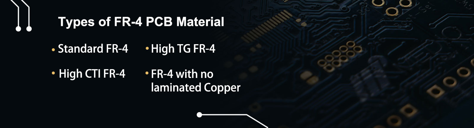
There are four different types of FR-4 material available in the market based on individual properties, they are listed:
Standard FR-4 refers to the normal material, with heat resistance ranging from 150-160 Celsius. The properties and advantages of the standard FR-4 are listed above.
High TG FR-4 stands for high glass transition temperature. PCBs made with high glass transition temperature FR-4 material have the ability to resist and maintain their shape at a temperature of 170 ℃. In this type of base material, Higher TG is achieved through extra-efficient lamination. PCBs made with high TG FR-4 material have the ability to resist and maintain their shape at a temperature of 170 ℃. The standard Fr-4 material is a great insulator and flame retardant, but still, it has some limits when exposed to high power, voltage, or heat. If a certain limit exceeds, the materials insulating properties can get weakened. It can start conducting electricity instead of insulating it. Thereby high Tg FR-4 is used to avoid these unwanted circumstances.
Applications of High TG FR-4 Material:
The Comparative Tracking Index is the limit to which the FR-4 or any other insulating material can resist the unwanted current flowing between the tracks on the printed circuit board. The CTI value indicates how resistive PCB base material is against unpleasant environmental and electrical conditions such as moisture and leakages on board. The high CTI material with a maximum value of 600 V ensures that the base is more resistant and can withstand harsh environmental and electrical conditions.
Applications of High CTI FR-4 Material:
This type of FR-4 is a little different with distinct functions. As the name itself explains that this type of material has no copper lamination on it and, therefore, is used to insulate and support other boards, etc.
Though FR-4 PCBs are widely famous for their quality and low prices, providing good electrical and mechanical properties. The application of FR-4 PCB material is vast. From small circuit boards to large and complex systems, they have been in use for years. But could this material be the answer for every type of circuit, especially for the circuits with high-frequency requirements?
> Related reading: If you’re choosing materials for RF / high-frequency designs, see Rogers vs FR4: How to Choose PCB Materials for High-Frequency Designs.
When it comes to high-frequency laminate, there are multiple factors to consider, such as:
In many passive circuits, the signal loss increases with the gain in frequency. As we know that FR-4 PCB material has a higher dissipation factor (Df ) than laminates designed for high-frequency use, and due to this, the circuits fabricated on FR-4 suffer more loss in signal than similar circuits constructed on a PCB with high-frequency laminate material. The typical value for signal loss is about 0.020 for FR-4 and about 0.004 for a high-frequency laminate or any other base material with a dissipation factor that is about one-fourth of FR-4. The difference between the signal loss of both materials due to the dissipation factor is huge and can affect the performance of the whole system. Therefore, the capacity of designs to tolerate signal loss is different and majorly depends on the loss budget of individual projects.
Bottom Line: Due to the high dissipation factor (Df), signal loss is higher in standard FR-4 PCBs as compared to high-frequency laminates.
Stable impedance is crucial for many designs, such as high-speed digital circuits. Stable impedance is achieved by maintaining a stable dielectric constant (DK) across the substrate. The dielectric constant in FR-4 varies with changes in frequency. In FR-4 PCB material, the dielectric constant (Dk) may change as frequency increases, and it can also be influenced by resin system, glass weave style, and manufacturing tolerances. Though, the dielectric constant tolerances for high-speed materials are less than 2%, whereas FR-4 can fluctuate up to 10%. Therefore, FR-4 makes it almost impossible to achieve stable impedance. On the other hand, high-frequency laminates provide a stable dielectric constant across the whole board. The stable dielectric constant helps in maintaining stable impedance.
Bottom Line: Due to the unstable dielectric constant, FR-4 is unable to provide a stable impedance. Hence, it cannot be used for circuits that require controlled impedance. In this case, high-frequency laminates are great options to avail.
Just like the dielectric constant, FR-4 also has a higher thermal coefficient of the dielectric constant (TCDK) too. TCDK is a way to conclude how much the Dk changes over a given temperature. For FR-4, it is typically 200 parts per million (ppm) per Celsius. This number seems too little to be worried about, but a wide temperature range can result in huge variations. On the other hand, high-frequency lamination provides an 80% smaller value of 40 parts per million (ppm) per Celsius. This property of FR-4 made it incapable of being used with designs that require little variations over a wide temperature range. In this case, high-frequency lamination is best to use.
Bottom Line: FR-4 has a higher TCDK compared to high-frequency lamination, which makes it incapable of using in circuits that require little variation over a wide range of temperatures.
In comparison to high-frequency laminate, FR-4 has so many downsides. But there are still some properties that make FR-4 stand out. Such as, moisture absorption of FR-4 is higher than high-frequency lamination. The moisture absorption property of the substrate is crucial to note while working with marine and outdoor applications and moisture-sensitive devices or circuits.
Bottom Line: FR-4 has a higher ability to absorb water. Hence, it is better to use FR-4 for circuits where moisture could be a problem.
On a wavelength-dependent circuit, the results of using FR-4 or high-frequency lamination could be different. On a wavelength-dependent circuit such as a high-frequency circuit, the dielectric constant will affect the size of the whole circuit. Therefore, circuit boards with higher Dk can produce smaller circuits and vice versa. As we know, the dielectric constant value of the FR-4 is about 4.5, which is still higher than most PTEF high-frequency materials but lower than several high-frequency laminates, which can provide a dielectric constant (Dk) of about 6.15-11.0. So, high-frequency laminate or any other material with such high Dk can save up to 25-30% or much more of the size of a circuit board compared to FR-4.
Bottom Line: For wavelength-dependent devices such as radio, filters, power amplifiers, etc. High-frequency laminate is better to use due to the high dielectric constant, which will help to reduce the size of the circuit.
In a nutshell, the difference between FR-4 PCB material and high-frequency laminate is mainly of dielectric constant (Dk) and dissipation factor (Df). High-frequency laminate provides high dielectric constant Dk and low dissipation factor Df, which makes it perfect to use mainly for Radio PCBs, antennas, filter circuits, power amplifiers, and high-speed digital PCBs.
We all know that FR-4 is a standard set by National Electrical Manufacturers Association (NEMA) for glass-reinforced epoxy laminate material. But it is not the only substrate to use as a PCB base.
As far as it is concerned about simple and basic circuit designs that run at low frequencies and are not subject to extreme environmental conditions, FR-4 might be a great choice. But for modern and high-frequency circuits with more accurate material requirements, there are other materials available to consider.
Why do we need FR-4 alternative materials? Not every circuit is the same, and neither their specifications are. Some boards might have high-temperature requirements, and some could have high frequency. The desired requirements of substrate change from circuit to circuit, and a single material cannot fulfill all of them.
To understand and compare FR-4 with other substrate materials, first we need to understand the limitations of FR-4.
The limitations of FR-4 do not make this material unsuitable for every circuit. These limitations only affect a particular circuit design. The industry using FR-4 on a big scale is proof of FR-4 PCB material's credibility.
Let's get back to the topic. We have understood the limitations; it's time to address and compare some other PCB substrate materials.
MCPCB is an abbreviation for Metal Core Printed Circuit Board. MCPCB uses either Aluminum or copper as metal core base material. The structure of PCB is simple. It is made up of a thermal insulating layer, metal plate, and metal copper foil with high thermal conductivity. MCPCB provides excellent heat dissipation and mechanical support. The copper-based MCPCB works better than Aluminum based MCPCB but is slightly high in price.
Application: Due to its High Thermal Conductivity, MCPCB is suitable for high-temperature exposing circuits.
Here is a table emphasizing the available properties of Aluminum based Metal-Baked PCB Material.
| Properties of the Material | Values |
|---|---|
| Aluminum thickness | 0.8 - 2.0 mm |
| Thermal conductivity | 1.5 W/(m·K) and 2.0 W/(m·K) |
| Peeling strength | >9 lb/in |
| Solder resistance | SF: 288 ℃, >180 sec |
| Breakdown voltage | >3000 V |
| Dielectric loss angle | 0.03 |
| Flammability | UL 94V-0 |
Ceramic PCBs use ceramic as the base material, which provides high thermal conductivity and minimal Coefficient of Thermal Expansion (CTE). The alumina, aluminum nitride, and beryllium oxide help transfer heat from their source to the entire board surface. Along with providing high thermal conductivity, Ceramic PCB material also provides a stable dielectric constant (Dk), which means controlled impedance. Ceramic PCBs serve exceptional high-frequency performance.
The ceramic PCB is extremely versatile and simple. It can overcome complex designs in simple ways with increased performance and product life. Ceramic PCBs have their applications in multiple products, like memory modules, missiles, and aerospace products.
There are three types of ceramic PCBs.
Composite Epoxy Material (CEM) is another alternative material to FR-4 PCB material. CEM is a composite material made up of woven glass fabric surfaces and a non-woven glass core combined with epoxy synthetic resin.
There are five types of Composite Epoxy Material (CEM):
CEM-1: It is a low-cost material with flame-retardant properties. CEM-1 is a cellulose-paper-based laminate with a single layer of woven glass fabric. CEM-1 is only useful for single-layer PCB manufacturing.
CEM-2: CEM-2 also has a cellulose paper core and woven glass fabric surface. It is kind of similar to CEM-1.
CEM-3: It is an epoxy resin copper-clad laminate that uses non-woven glass fabric as base material. CEM-3 is highly similar to FR-4. It is a fire retardant and contains almost similar properties as FR-4. CEM-3 has its application in single to multi-layer PCB.
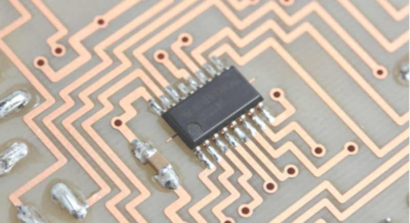
An integrated circuit and passive components were hand-soldered onto CEM-3.
CEM-4: It is similar to CEM-3. The only drawback is that this material is not flame-retardant.
CEM-5: This material has a polyester woven glass core.
Composite Epoxy Materials, due to their type three, are eventually CEM-3 considered as the complete replacement for FR-4. The low cost of CEM-3 strengthens the material enough to replace FR-4 PCB. But CEM-3 cannot completely replace FR-4 as manufacturers do not recommend this substrate for multi-layer boards. Therefore, it is a recommended and reliable substrate only for single or double-layer PCBs.
High-Frequency Laminates are a well-known solution for high-speed and controlled impedance boards. High-Frequency Laminates provide minimal signal loss and a high thermal coefficient of dielectric constant (TCDK) as well as stable dielectric constant (Dk). These specifications of high-frequency laminate make it a perfect substrate for drone RADAR, wireless metropolitan area networks, remote sensing, power amplifiers, and high-speed digital PCBs.
High-Frequency Laminates are a must for circuits that have to provide very long channel lengths, such as backplanes and server motherboards.
The two most commonly used high-frequency printed circuit board substrate materials are PTEF-based laminate known as Teflon and Megtron. Using one of these two high-frequency PCB laminates might be the best choice for devices with long routing channels.
While selecting any PCB substrate material, it's crucial to consider several factors such as its thickness, weight, available space to design, flexibility, and impedance. These factors are discussed in detail below.
The thickness of a PCB board plays a vital role in acquiring the desired results. The thickness of a PCB is usually measured in millimeters. For example, the thickness available for FR-4 PCB sheets ranges from 0.127 mm to 3.175 mm or 0.005 inches to 0.125 inches. However, the thickness of each board varies depending on the requirements of the project.
The thickness of a board may not sound like a significant factor to pay attention to. However, in reality, the thickness of the board affects the overall board functionality. That is why several factors should be considered while determining the thickness of the board for each and every individual design. Some of the factors are:
Two PCBs require an edge connector to join them with each other or another matching socket. The connectors are available only in limited sizes. Hence only fits a particular set of PCB thicknesses. It might be a limiting factor to PCB thickness. If the existing PCB is redesigning and is part of an old system, the thickness of the PCB must be checked twice. That is why it is considered the fundamental reason to pay attention to the board's thickness after finalizing the circuit design and before ordering it to manufacture.
Multiple devices such as Bluetooth accessories, remotes, and memory modules do not have much space. For these types of devices, a thinner PCB is the best solution. Thinner PCBs are not only considered efficient for small electronic devices. But they are also efficient for large modules to save space within them.
Flexibility is another vital factor to consider while choosing the thickness of FR-4 PCB material. The thinner the board, the more flexible it is. Due to heat, highly flexible and thinner PCBs usually face a high risk of bending and change of angles during soldering. Heat management should be a priority in these designs.
Since thinner PCBs show efficient performance against regularly stressed and flexible products. They have wide applications in medical and automotive devices.
The flexibility requirements of boards vary from design to design. However, the thickness or flexibility of a PCB should finalize by considering its applications and environmental conditions.
Some high-frequency/high-speed boards require controlled impedance. We know that a stable dielectric constant (Dk) and low (thermal coefficient of dielectric constant) help to achieve controlled impedance. It is crucial to keep the thickness of FR-4 material balanced. Thin PCBs face high heat and increased thermal coefficient of dielectric constant (TCDK), which causes fluctuating dielectric constant (Dk). Due to this, it is critical to maintain the thickness of the PCB to achieve a low dielectric constant (Dk).
The thickness of the Fr-4 material has its effects on components. Most components, mainly Through Hole components, work better with thinner PCBs than thicker ones.
Thin boards are light in weight and reduced in size, hence convenient for consumer electronics. It is easy to carry them, and they also reduce the shipment cost of the material. But thin boards are not an answer to large boards. The increased size of the board with a thin structure can cause fractures and bend in the PCB. While, extra thick boards can take a large surface and increase the overall weight of the module/device, which has its own consequences.
The mentioned properties and qualities of FR-4 make it a perfect substrate for PCBs. FR-4 can provide a low-cost PCB with exceptional chemical and environmental properties.
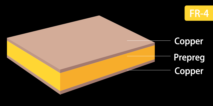
In PCBs, FR-4 functions as the primary insulating material. The FR-4 provides the base upon which the designers print the circuit. Then this basic structure made with FR-4 material is laminated with single or multiple layers of copper foil using heat and adhesive material. The copper lamination completes the board and might be single or double-sided, depending on the circuit design of the board. Complex PCBs could possibly have multiple FR-4 and copper foil layers before being covered with a solder mask layer. The solder mask layer is applied to protect the PCB from oxidation and to prevent solder bridges from mating between closely spaced solder pads.
FR-4 is a low-cost substrate with good properties. But it cannot be a proper fit for every individual board. Therefore, the FR-4 material should be avoided when these qualities are required.
FR-4 has low thermal conductivity. Due to low thermal conductivity, heat does not move rapidly. Hence, heat dissipation is a problem in FR-4 printed circuit boards. As a result, PCBs made with FR-4 material cannot tolerate higher temperatures, i.e., more than 170 ℃. Here, the point to note is that 170 ℃ is provided by the special type of FR-4 material known as High TG (High Glass Transition Temperature) FR-4 material, while the standard FR-4 material provides Tg of 130 ℃ to 140 ℃.
For PCBs that require excellent temperature resistance, Metal-core or Metal-backed PCB Material is considered best to use.
Standard FR-4 material has a low glass transition temperature. While lead-free soldering requires a higher melting point. In this case, standard FR-4 PCB material is preferred to avoid while high TG FR-4 material could be used.
Due to the high dielectric constant and high dissipation factor FR-4, PCB material provides high signal loss of a typical value of about 0.020 (tan(δ)) @ 1GHz. The signal loss is directly proportional to the frequency means that the higher the frequency, the greater the signal loss. In such types of high-speed/high-frequency circuits, high-frequency laminate is recommended by manufacturers best to use.
> For a practical decision framework (frequency, trace length, impedance tolerance, and hybrid stackups), read: Rogers vs FR4: How to Choose PCB Materials for High-Frequency Designs.
These are the NextPCB's FR-4 PCB material manufacturing capabilities:
FR-4 is a dielectric glass-reinforced epoxy laminate material used as a base material for insulation in printed circuit boards. This PCB substrate is a low-cost, most commonly used material with good electrical and environmental properties.
FR-4 is a suitable substrate for several general-purpose PCBs, but when it comes to high-speed/high-frequency PCBs, FR-4 PCB material has limitations. These limitations include a higher dielectric constant, higher dissipation factor, and lower glass transition temperature than high-frequency laminates.
There are other substrates available in the market that can overcome the limitations of FR4 PCB material, such as Metal Core, Ceramic, Composite Epoxy Material, and High-Frequency Laminates. These FR-4 substrate alternatives have pros and cons. Still, if chosen by considering the requirements and functionality of the design, these PCB base materials can provide exceptional performance.
>> Recommend reading: Is Your Design High-Speed or High-Frequency? A Simple Checklist
>> Ceramic PCB vs FR4 vs Metal-Core: Substrates for Thermal Management
If you're seeking FR-4 PCBs or PCBs made with any other material NextPCB can help you to provide what suits you best. NextPCB is one of the most experienced PCB manufacturers around the globe, providing high-quality PCB products with dedicated customer service. NextPCB also comes up with turnkey services, including components sourcing, PCB prototyping/PCB manufacturing, PCB assembly, quality testing, and the final shipment. NextPCB could meet your needs from PCB prototyping to small PCB production or mass PCB production.

Still, need help? Contact Us: support@nextpcb.com
Need a PCB or PCBA quote? Quote now

