NextPCB Capabilities
 PCB Assembly
 Layer Buildup
 SMD-Stencils
 PCB Design-Aid & Layout
 Mechanics
 Quality
 Drills & Throughplating
 Factory & Certificate





Rogers 5880 (RT/duroid 5880): Dielectric Constant, Loss Tangent, and Design Guide
Rogers RT/duroid 5880, commonly shortened to "Rogers 5880" in search and in datasheets, is a glass microfiber reinforced PTFE composite built for high-frequency and broadband RF/microwave circuits. Its defining numbers are a dielectric constant (Dk) of 2.20 ± 0.02 and a dissipation factor (Df) of 0.0009 at 10 GHz — among the lowest loss figures of any reinforced PTFE laminate on the market. This guide breaks down the datasheet values, compares 5880 against other Rogers PCB materials, and walks through when it is (and isn’t) the right choice for your board.
What Is Rogers 5880?
Rogers RT/duroid 5880 is a PTFE (polytetrafluoroethylene) laminate reinforced with randomly oriented glass microfibers. The random fiber orientation is what keeps the dielectric constant uniform in both the X and Y directions, which is why the material is described as isotropic. Rogers Corporation designed 5880 specifically for stripline and microstrip circuits that need very low dielectric loss, and it has been a standard reference material in the RF/microwave industry for decades.
Unlike standard FR-4, 5880 is not an epoxy-glass laminate — it is a soft PTFE composite, which changes how it drills, etches, and bonds during fabrication. If you are still deciding whether your design even needs a PTFE laminate versus a standard glass-epoxy board, the frequency node guide for switching from FR-4 to Rogers is a useful starting point before you narrow down to a specific grade like 5880.
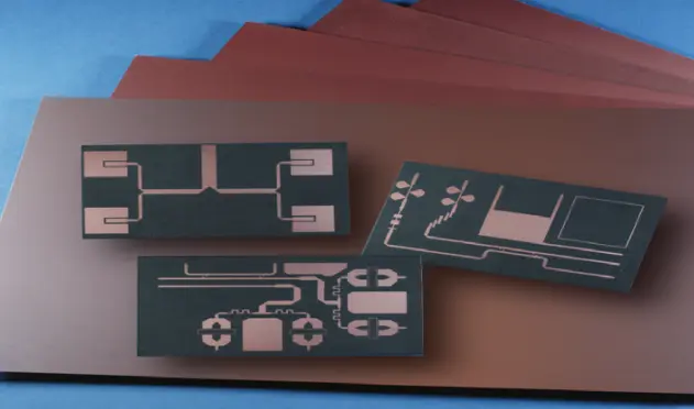
Rogers 5880 Dielectric Constant and Loss Tangent
The two numbers every RF designer looks up first are Dk and Df, since both directly affect impedance calculations and insertion loss.
| Property | Value | Test Condition |
|---|---|---|
| Dielectric Constant (Dk / εr), process value | 2.20 ± 0.02 | 10 GHz, IPC-TM-650 2.5.5.5 |
| Dielectric Constant (Dk), design value | 2.20 | 8–40 GHz, differential phase length method |
| Dissipation Factor (Df / tan δ) | 0.0009 | 10 GHz, IPC-TM-650 2.5.5.5 |
| Dissipation Factor (Df / tan δ) | 0.0004 | 1 MHz, IPC-TM-650 2.5.5.3 |
| Thermal Coefficient of Dk | −125 ppm/°C | −50°C to 150°C |
Two things stand out in this table. First, the design Dk of 2.20 stays stable from 8 GHz all the way up to 40 GHz, which is why 5880 shows up so often in millimeter-wave and Ku-band designs. Second, the loss tangent at 10 GHz (0.0009) is roughly 4–13x lower than typical FR-4, which is the real driver behind 5880’s use in long RF traces, antenna feed lines, and broadband modules where every fraction of a dB of insertion loss matters.
Key Material Properties at a Glance
| Property | Typical Value |
|---|---|
| Base material | PTFE reinforced with glass microfibers |
| Water absorption | 0.02% |
| Volume resistivity | 2 × 10⁷ MΩ·cm |
| Copper cladding | Electrodeposited copper, typically 1/4 oz to 2 oz/ft² per side; rolled copper foil available for tighter electrical tolerance |
| Dimensional stability / chemical resistance | Easily cut, sheared, and machined; resistant to solvents and reagents used in etching and plating |
These properties come from Rogers Corporation’s published RT/duroid 5870/5880 data sheet. If you need the full document for a design review or compliance file, Rogers Corporation hosts the official PDF on rogerscorp.com.
Rogers 5880 vs. Other High-Frequency Laminates
5880 is one of several Rogers grades that get shortlisted for the same high-frequency projects, so it’s worth knowing where it sits relative to its closest siblings.
- 5880 vs. RT/duroid 5870: The two materials share the same PTFE/glass-microfiber construction, but 5870 has a higher Dk (2.33) and a higher loss tangent (0.0012 at 10 GHz) than 5880 (2.20 Dk / 0.0009 Df). In practice, 5880 is the lower-loss option of the pair and is preferred when insertion loss is the tighter constraint.
- 5880 vs. RO4003C: RO4003C is a hydrocarbon/ceramic laminate rather than PTFE, with a higher Dk (~3.38) and higher loss than 5880, but it is easier to fabricate with standard FR-4-style processes and costs less. For a deeper side-by-side on RO4003C’s properties and sourcing, see the Rogers 4003C manufacturing and sourcing guide.
- 5880 vs. FR-4: FR-4’s Dk varies with frequency and can run 2–3x higher in loss tangent, which makes impedance control and signal loss unpredictable above a few GHz. The Rogers vs. FR-4 comparison guide walks through the full decision criteria if you’re still weighing whether you need a Rogers laminate at all.
For the complete lineup of Rogers materials NextPCB fabricates — not just 5880 — see the Rogers PCB manufacturing page. If you're still comparing across vendors and material families — Rogers, Megtron, Isola, and others — the Advanced PCB Materials Library lays out the full set side by side.
Common Applications
Because of its low loss and stable Dk across a wide frequency range, Rogers 5880 shows up most often in:
- Microstrip and stripline circuits
- Point-to-point digital radio antennas
- Military and commercial radar systems
- Missile guidance systems
- Millimeter-wave applications
- Broadband and antenna feed networks where insertion loss must stay tightly controlled
When to Choose Rogers 5880 for Your Design
5880 tends to be the right call when:
- Your operating frequency runs from a few GHz up through Ku-band or higher, and dielectric loss directly limits your link budget or signal range.
- You need a low, stable Dk (2.20) that won’t drift across a wide bandwidth — important for broadband antennas and multi-octave designs.
- Your board will see humid or variable-temperature field conditions, where 5880’s low moisture absorption keeps electrical performance predictable.
It’s usually not the most cost-effective choice when your design sits below a few GHz and standard hydrocarbon-ceramic laminates or even high-Tg FR-4 can meet the loss budget — in those cases, the FR-4-to-Rogers frequency threshold guide can help you confirm whether you actually need a PTFE-grade material. For AI server, high-speed digital, and mixed-signal boards where Megtron and other low-loss laminates are also in the running, the high-speed PCB materials comparison covers how 5880-class materials stack up against those alternatives.
Thickness, Copper Weight, and Fabrication Notes
RT/duroid 5880 is supplied as sheet stock and roll stock in a range of standard dielectric thicknesses, with copper cladding available in several weights and in either electrodeposited or rolled copper foil. When specifying a 5880 board for fabrication, you’ll typically need to confirm:
- Dielectric thickness and thickness tolerance
- Copper foil type (rolled vs. electrodeposited) and weight per side
- Whether the design is single-layer, multilayer, or a mixed stackup bonded to FR-4 or another material
- Surface finish requirements, since PTFE surfaces need a plasma or chemical treatment step before bonding or plating
| Specification Item | Technical Capabilities / Details |
|---|---|
| Layer Count | 2-6 layers; supports pure multilayer and hybrid stack-ups |
| Board Thickness | 0.203mm - 2.4mm (refers to base substrate thickness for 2-layer boards) |
| Material Types | Rogers 4350B, Rogers 4003C |
| Min. Trace Width/Spacing | 3.5mil / 3.5mil |
| Min. Hole Size | 0.15mm |
| Solder Mask Colors | Green, Blue, Red, Yellow, Black, Matte Black, White |
| Via Coverage | Via plugging with ink, via plugging with resin + copper capping (POFV) |
| Surface Finish | ENIG (1μ" - 3μ"), OSP, Immersion Tin, Immersion Silver |
| Special Processes | Castellated holes (half-cut), Edge plating, Press-fit holes, Blue mask, Carbon ink |
| Testing Methods | AOI + 4-wire low resistance flying probe full testing |
NextPCB fabricates Rogers 5880 boards across standard thickness and copper-weight options, including mixed-material stackups bonded to FR-4 for cost-sensitive multilayer designs. For current thickness ranges, minimum trace/space, and lead times, check the Rogers PCB capability page or request a quote with your stackup for exact confirmation.
FAQ
What is the dielectric constant of Rogers 5880?
Rogers 5880’s dielectric constant (Dk) is 2.20 ± 0.02 at 10 GHz, with a design Dk of 2.20 that stays stable from roughly 8 GHz to 40 GHz.
What is the loss tangent (dissipation factor) of Rogers 5880 at 10 GHz?
The dissipation factor of Rogers 5880 is 0.0009 at 10 GHz, and 0.0004 at 1 MHz — among the lowest loss figures of any reinforced PTFE laminate.
Is "Rogers 5880" the same material as "RT/duroid 5880"?
Yes. "Rogers 5880" is the shorthand commonly used in search and in the industry for Rogers Corporation’s RT/duroid 5880 laminate.
What is Rogers 5880 used for?
It is most commonly used in microstrip and stripline RF circuits, radar systems, antenna feed networks, point-to-point digital radio, and other high-frequency or broadband applications where dielectric loss needs to stay very low.
How does Rogers 5880 compare to Rogers 4003C?
5880 is a PTFE laminate with a lower Dk (2.20) and lower loss than RO4003C’s hydrocarbon/ceramic construction (Dk ~3.38), but RO4003C is easier and cheaper to fabricate with standard processes. See the Rogers 4003C guide for a full comparison.
Where can I find the official Rogers 5880 datasheet?
The official RT/duroid 5870/5880 data sheet is published by Rogers Corporation on rogerscorp.com and lists the full set of tested electrical, mechanical, and thermal properties.
Need Rogers 5880 fabricated to your stackup? Compare thickness, copper, and layer-count options on the Rogers PCB page, or request a quote directly with your Gerber files and material callouts.