High-Frequency and High-Speed PCB Material Selection Guide
In PCB design, the choice of substrate directly determines signal integrity and manufacturing cost. Many hardware engineers face a critical question early in the design phase: At exactly what frequency node must we abandon the low-cost standard FR-4 and switch to high-frequency, low-loss materials like Rogers?
The short answer is: This is not a single absolute value. Generally, 1 GHz is the starting point to pay attention to loss, and 10 GHz is the hard node where the Radio Frequency (RF) field must switch to Rogers. In addition, for High-Speed Digital (HSD) applications, speeds above 10 Gbps trigger a rigid demand for low-loss materials and the resolution of the "glass weave effect".
- Table of Contents
- 1. Why Can't High-Frequency Signals Use Standard FR-4?
- 2. Critical Frequency Nodes and Two "Technology Tracks"
- 3. Core Technical Parameters Comparison (Engineering Reference)
- 4. Engineering Cost Reduction Killer Tool: Hybrid Stackup
- 5. Summary
1. Why Can't High-Frequency Signals Use Standard FR-4?
Standard FR-4 has three fatal limitations in high-frequency/high-speed environments:
- High Dielectric Loss (Df / tanδ): The Df value of FR-4 is usually around 0.020. As the frequency rises, the signal energy quickly converts into heat, causing severe Insertion Loss.
- Dielectric Constant (Dk) Instability: The Dk value of standard FR-4 fluctuates greatly at different frequencies and temperatures, which directly leads to impedance out of control and phase drift.
- Glass Weave Skew Effect: This is the invisible killer of high-speed digital design. The glass weave of standard FR-4 is uneven. If a differential pair is routed over the glass fiber (high Dk) and pure resin (low Dk) respectively, it will cause severe phase Skew, directly leading to a closed eye diagram.
2. Critical Frequency Nodes and Two "Technology Tracks"
When evaluating the switching node, we must distinguish between two completely different technology routes: Radio Frequency/Microwave (RF/Microwave) and High-Speed Digital (HSD).
1) Safe Zone: < 1 GHz (Standard FR-4)
- Applicable Scenarios: Low-frequency control circuits, power boards, general consumer electronics.
- Engineering Advice: Below 1 GHz, the signal wavelength is longer, and the loss of FR-4 is within an acceptable range. As long as the traces are not extremely long, cost control is the primary consideration, and standard FR-4 is fully capable.
2) Transition Zone: 1 GHz - 10 GHz / 1 - 10 Gbps (High-Performance FR-4 or Mid-Loss Materials)
- Applicable Materials: High-performance epoxy resin systems (such as Isola 370HR, FR408HR).
- Engineering Advice: In this frequency band, loss begins to appear. Engineers usually choose High-Tg FR-4 to improve thermal reliability and basic impedance control capabilities.
- Note: At this time, the material still belongs to the "Mid-Loss" level. Although it is more stable than standard FR-4, it has not yet adopted advanced resin systems.
3) Absolute Node: > 10 GHz / > 10 Gbps (Rogers or Ultra-Low Loss Materials)
Once crossing this threshold, PCB design enters the deep water zone of high frequency/high speed, and the selection logic begins to branch:
A. RF/Microwave Track (Carrier Frequency > 10 GHz)
- Core Requirements: Extremely high Dk stability, extremely low Df.
- Mandatory Materials: Rogers series (such as RO4350B, RO3003) or similar high-frequency microwave boards.
- Reason: RF applications are usually narrowband or single-frequency points (such as 24GHz radar, 5G base stations). The hydrocarbon/ceramic/PTFE systems provided by Rogers can ensure that the impedance tolerance is within an extremely small range, which is absolutely impossible for FR-4 to achieve.
B. High-Speed Digital Track (Speed > 10 Gbps, e.g., PCIe 5.0, 112G PAM4)
- Core Requirements: Broadband loss control, phase consistency, multi-layer board processability.
- Mandatory Materials: Ultra-Low Loss materials (such as Panasonic Megtron 6/7/8 or Isola Tachyon).
- Reason: High-speed digital systems are usually 20-30 layer high-density boards, which have extremely high requirements for the drilling processability of the materials. At this time, you do not necessarily have to choose Rogers, but you must choose PPE/PPO system materials with Spread Glass technology to eliminate the phase skew caused by the glass weave effect.
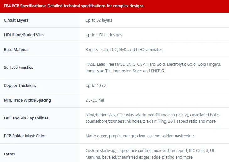
3. Core Technical Parameters Comparison (Engineering Reference)
The following table compares the core performance of FR-4 with mainstream high-frequency/high-speed materials at 10 GHz:
| Material System |
Dk (10GHz) |
Df (Loss Tangent) |
Core Advantage |
Main Track |
| Standard FR-4 |
3.8 – 4.8 |
0.016 - 0.020 |
Ultimate low cost |
General low frequency |
| Isola 370HR |
3.92 |
0.025 |
Thermal stability, cost balance |
Mid-frequency / High-performance FR-4 |
| RO4350B |
3.48 |
0.0037 |
Excellent impedance control, broadband stable |
RF / Microwave base stations |
| Megtron 6 |
3.40 - 3.61 |
0.004 |
Ultra-low loss, low skew |
High-speed servers / Core switches |
| RT/duroid 5880 |
2.20 |
0.0009 |
Ultimate ultra-low loss |
Millimeter wave / Satellite communications |
Note: For more detailed data, please consult your PCB manufacturer.
*Professional Tip: The nominal Process Dk of RO4350B is 3.48, but when performing microwave impedance simulation (such as HFSS/ADS), the official strongly recommends using the Design Dk of 3.66 to obtain accurate results.
4. Engineering Cost Reduction Killer Tool: Hybrid Stackup
Using Rogers materials entirely will cause the bare PCB cost to surge 3-5 times. In actual engineering, NextPCB often recommends and manufactures Hybrid Stackup solutions for customers:
- Solution Concept: Use Rogers RO4350B on the critical RF signal layers (such as L1-L2), while continuing to use low-cost, high-performance FR-4 on the non-critical internal logic signal layers and power/ground layers.
- Implementation Process: The heterogeneous boards are perfectly bonded through special high-frequency prepregs (such as the Rogers RO4450 series).
- Benefits: This method can ensure 100% of the critical RF signal integrity while significantly reducing the overall BOM cost by more than 40%.
5. Summary
When deciding to switch from FR-4 to higher specification boards, please follow the following core principles:
- Analog RF Applications: Take 10 GHz as the hard indicator. Above 10 GHz, you must switch to dedicated microwave materials like Rogers.
- Digital High-Speed Applications: Take 10 Gbps as the threshold. Not only should you pay attention to dielectric loss, but you must also choose low-loss materials with "spread glass" technology to eliminate the fatal glass weave effect.
- Cost-Sensitive Projects: Give priority to considering and designing a Hybrid stackup solution.
About NextPCB's Manufacturing Capabilities
> Standard PCB Manufacturing Capabilities >> Advanced PCB Manufacturing Capabilities
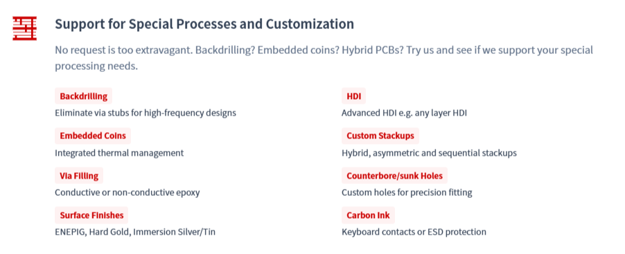
Processing high-frequency materials and heterogeneous material hybrid pressing poses extremely high requirements on the PCB manufacturer's etching accuracy, lamination registration, multiple lamination cycles, and drilling processes. NextPCB has profound experience in Rogers / Megtron / FR-4 hybrid stackup manufacturing, keeps mainstream high-frequency and high-speed boards in stock, and supports extremely strict impedance control requirements.
If you encounter bottlenecks in high-frequency PCB selection or Stackup design, welcome to contact NextPCB's technical engineering team for free DFM (Design for Manufacturability) evaluation and stackup optimization suggestions.
FAQ: FR-4 vs. Rogers – Solving Your Frequency Dilemma
Q1: At what frequency point is it mandatory to switch from FR-4 to Rogers?
A: The industry "gray area" typically starts between 3GHz and 5GHz.
- Below 2GHz: Standard FR-4 is usually sufficient for most low-power IoT, BLE, or control circuits.
- 3GHz – 10GHz: This is the critical transition zone. Standard FR-4’s high Dissipation Factor ($Df \approx 0.015 - 0.020$) leads to significant signal attenuation. If your traces are long, Rogers or High-Speed/Low-Loss FR-4 is highly recommended.
- Above 10GHz: For X-Band radar, 5G mmWave, or high-speed backplanes, Rogers (PTFE-based materials) is mandatory. FR-4’s Dielectric Constant ($Dk$) fluctuates too wildly at these frequencies, causing severe impedance mismatch.
Q2: Are there factors other than frequency that dictate the need for Rogers materials?
A: Yes. Frequency isn't the only driver. You should consider Rogers if your project requires:
- Tight Impedance Control: Rogers offers extremely stable $Dk$ (typically $\pm 0.05$ tolerance), which is vital for sensitive RF matching.
- Thermal Management: Rogers has superior thermal conductivity and a lower Coefficient of Thermal Expansion (CTE), making it ideal for high-power RF amplifiers that generate significant heat.
- Moisture Resistance: In high-humidity environments, FR-4 absorbs moisture, which drastically alters its dielectric properties. Rogers remains stable under such conditions.
Q3: Rogers is significantly more expensive. Are there any cost-effective alternatives?
A: Absolutely. The "Reddit-favorite" solution is the Hybrid Stack-up. Instead of a full-Rogers board, you can use a high-frequency Rogers laminate for the outer signal layers while using standard, inexpensive FR-4 for the inner structural and ground layers. This approach can save you 30% to 50% in material costs without sacrificing RF performance.
Q4: Which high-frequency materials does NextPCB support for manufacturing?
A: NextPCB provides professional-grade fabrication for a wide range of high-frequency laminates, including:
- Rogers 4000 Series: (e.g., RO4350B, RO4003C) – The industry standard for performance and processability.
- Taconic & Arlon: For specialized PTFE requirements.
- Advanced Hybrid Build-ups: We specialize in bonding Rogers with FR-4 to optimize your project's cost-to-performance ratio.

 NextPCB Capabilities
 PCB Assembly
 Layer Buildup
 SMD-Stencils
 PCB Design-Aid & Layout
 Mechanics
 Quality
 Drills & Throughplating
 Factory & Certificate
 PCB Assembly Factory Show
Certificate
PCB Assembly Factory Show
Certificate


 Surface

