
 Surface


Stacy Lu

 NextPCB Capabilities
Printed Circuit Boards
NextPCB Capabilities
Printed Circuit Boards
 PCB Assembly
 Layer Buildup
 SMD-Stencils
 PCB Design-Aid & Layout
 Mechanics
 Quality
 Drills & Throughplating
 Factory & Certificate
 PCB Assembly Factory Show
Certificate
PCB Assembly Factory Show
Certificate
Support Team
Feedback:
support@nextpcb.com


Introduction
Electrolytic Capacitors (E-caps) are indispensable components in circuit design, especially in power systems and low-frequency filtering, due to their ability to provide high capacitance in a small volume. For PCB engineers, understanding the types, critical parameters, and how to perform accurate derating design for electrolytic capacitors is key to ensuring long-term product reliability and performance. This report aims to provide a practical engineering guide, helping designers move from theory to bill of materials (BOM) preparation, ensuring the selection of electrolytic capacitors is readily implementable.
> Recommend reading: PCB Capacitors: Why Is It Important and How to Choose?
Contents
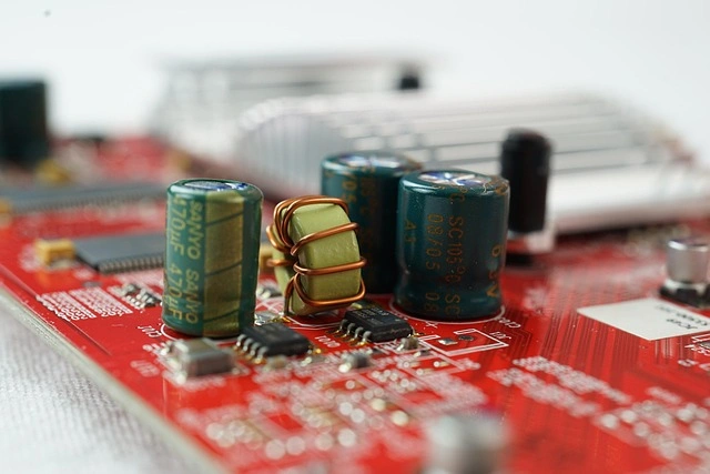
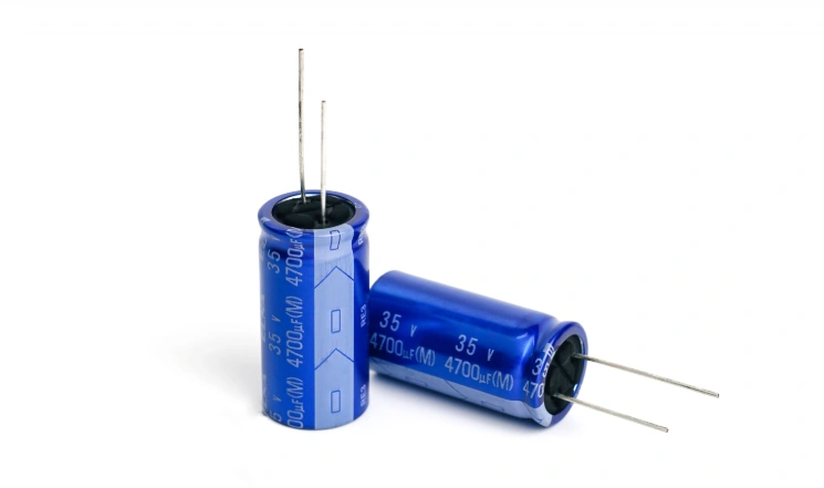
An electrolytic capacitor is a specialized type of polarized capacitor. Its basic structure is built around an anode (positive plate) made of a metal that forms an insulating oxide layer through anodization. This extremely thin oxide layer acts as the capacitor's dielectric. This process allows E-caps to achieve an extremely high capacitance-voltage product (CV) per unit volume.
Unlike electrochemical capacitors or supercapacitors that store energy through ionic conduction and electrochemical reactions, E-caps follow the traditional capacitor storage principle: they statically store electric energy through charge separation in the electric field within the dielectric oxide layer. The capacitor's second electrode (cathode) is formed by a non-solid or solid electrolyte.
Due to their asymmetrical construction, electrolytic capacitors are inherently polarized, and the anode potential must always be higher than the cathode potential. Unless explicitly permitted by the datasheet, the design should assume a reverse voltage tolerance of = 0 V; some specific series may tolerate a minimal reverse bias under strict conditions (e.g., ≤ 1–1.5 V, subject to time, temperature, or current limits), but this is not universally applicable. Exceeding the tolerance will destroy the dielectric layer, leading to internal overheating and eventual thermal failure.
Consequently, E-caps are inherently unsuitable for pure AC signal coupling applications. In the few AC coupling scenarios (e.g., in audio circuits), designers must ensure a positive DC bias voltage is superimposed on the anode to maintain normal operation and prevent performance degradation. This polarity restriction means that E-caps are mainly concentrated in power systems, unlike non-polarized film or C0G ceramic capacitors used in signal chains.
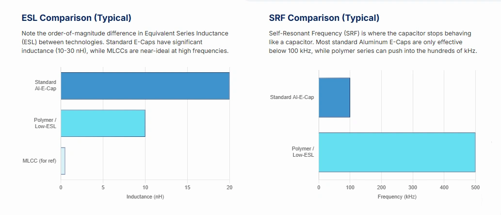
While E-caps achieve high volumetric capacitance through the oxide layer, their internal winding structure and lead length inevitably result in higher Equivalent Series Inductance (ESL). This internal inductance and the capacitance value jointly determine the capacitor's Self-Resonant Frequency (SRF), calculated by fR = 1 / (2π√(LESL · C)).
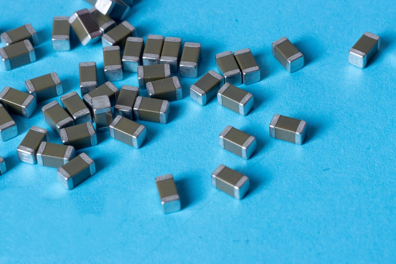
Most standard aluminum electrolytic capacitors have an SRF typically below 100 kHz, though individual small-volume, low-ESL polymer series can reach hundreds of kHz to the MHz range (device-dependent). Once the operating frequency exceeds the SRF, the capacitor transitions from capacitive to inductive behavior, impedance starts to rise, and filtering effectiveness is lost. Therefore, the primary function of E-caps is to provide Bulk Capacitance and low-frequency decoupling. High-frequency noise above several hundred kHz or MHz must be handled by components with extremely low ESL, such as Multilayer Ceramic Capacitors (MLCCs).
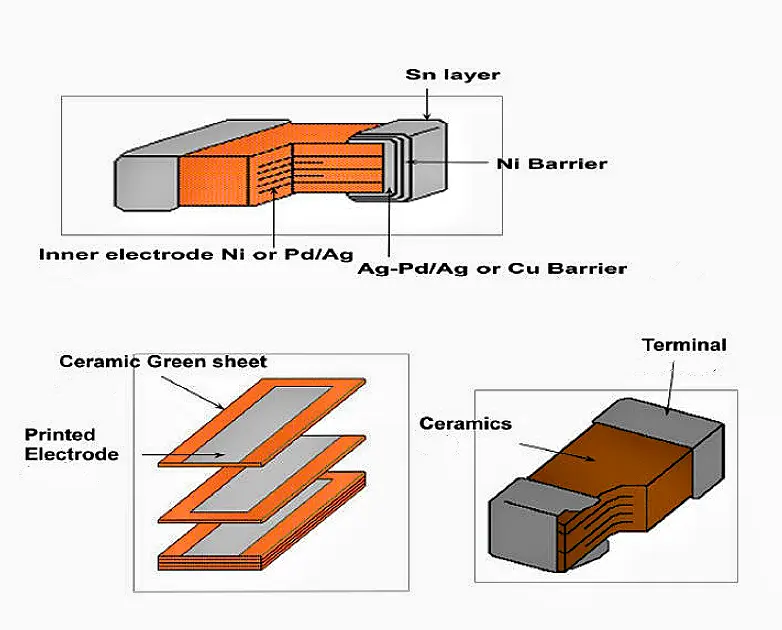
Image cited from: https://www.cnblogs.com/beiyhs/p/11200483.html
Hint: SRF and ESL parameters are strongly device-dependent. When modeling the Power Delivery Network (PDN) and selecting components, the specific datasheet specifications and actual measurements of the target part number should be the final basis.
Electrolytic capacitors are primarily divided into aluminum electrolytic capacitors (wet, solid polymer, hybrid polymer) and tantalum capacitors. Understanding their technical differences is a prerequisite for accurate selection.
Wet aluminum electrolytic capacitors offer excellent cost-effectiveness, providing the best microfarad-per-cost ratio among all capacitor types. They are particularly suitable for high-voltage applications ranging from 100 V to 400 V. However, their main drawback is a limited lifespan due to the liquid electrolyte, which gradually dries out or evaporates with time and temperature, leading to a drop in capacitance and a significant increase in Equivalent Series Resistance (ESR).
In applications, designers must strictly differentiate between “general purpose” and “switching type”. General purpose E-caps have higher ESR and ESL; if used in high-frequency Switched-Mode Power Supply (SMPS) designs, insufficient performance may lead to power failures. Therefore, SMPS requires dedicated “switching type” electrolytic capacitors designed for high ripple currents, ensuring lower ESR and ESL.
Due to their porous structure and ultra-thin dielectric layer, tantalum capacitors offer extremely high volumetric efficiency, meaning they are the smallest for a given capacitance value. Standard tantalum capacitors also have a wide operating temperature range (typically −55°C to 125°C), making them ideal for demanding applications like industrial and automotive electronics.
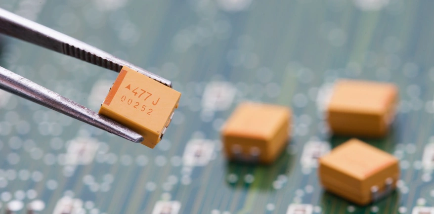
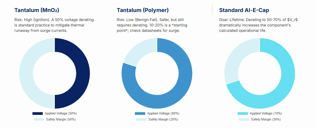
However, tantalum capacitors must be handled with extreme caution as they are highly sensitive to overvoltage. Overvoltage stress causes their failure mode to be a short circuit, which draws a large amount of current, potentially leading to a rapid increase in internal heat and ultimately ignition. This more dangerous failure mode compared to aluminum E-caps necessitates strict voltage derating for tantalum capacitors.
Tantalum capacitor derating depends on the cathode material:
With the proliferation of high-capacitance MLCCs and the cost advantage of aluminum E-caps, many modern designs tend to substitute the more expensive tantalum capacitors.
Polymer capacitors use a solid electrolyte, providing characteristics superior to wet E-caps, including:
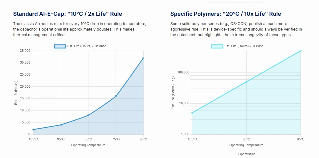
For non-polymer or general aluminum electrolytic capacitors, the “10°C reduction ≈ lifetime × 2” Arrhenius experience should still be used as a baseline.
These advantages make polymer capacitors the preferred choice for high-performance SMPS output filtering and high-speed digital circuits requiring fast transient response.
Hybrid polymer capacitors combine the benefits of conductive polymer and liquid electrolytes. They are designed to offer the low ESR and wide frequency response of solid-state capacitors while retaining the venting mechanism of wet capacitors, thus providing extremely high reliability and large current capability. These characteristics make them widely used in automotive electronics (e.g., AEC-Q200 certified series) and industrial control where both performance and reliability are critical.
The actual performance of an electrolytic capacitor is mainly determined by three interconnected parameters, which guide the specific specifications for BOM selection.
ESR is the ohmic resistance inside the capacitor, representing power loss during charge flow. Low ESR is critical because internal power dissipation P is proportional to the square of the ripple current and ESR (P = Iripple2 × ESR). High ESR leads to excessive internal temperature rise, accelerating electrolyte dry-out and shortening the lifespan.
For SMPS designs, low-ESR tantalum or polymer capacitors should be chosen to handle high currents. However, controlled ESR (typically between 10 mΩ and 100 mΩ) can provide necessary damping to prevent filter oscillation, thereby enhancing circuit stability.
ESL is primarily contributed by the capacitor's internal winding structure and lead length. At high operating frequencies, ESL becomes significant, causing the capacitor's impedance to rise with frequency. Standard E-caps typically have ESL values in the engineering range of 10 nH to 30 nH, while high-performance MLCCs can have ESL as low as 0.5 nH.
In PCB design, the designer must minimize external trace ESL by ensuring the capacitor is on the shortest decoupling path. High ESL is the fundamental limitation preventing E-caps from effectively handling high-frequency decoupling tasks.
> Recommend rading: PCB Electrolytic Capacitor Design: Layout, Routing & PDN Co-Optimization
SRF is the critical point where the capacitor's reactance changes from capacitive to inductive. Designers must ensure the target operating frequency is well below the capacitor's SRF.
Most aluminum electrolytic capacitors have a relatively low SRF, typically below 100 kHz. Only small-volume, low-ESL polymer series can push the SRF to the MHz range.
Figure: Typical ESL and SRF comparisons across capacitor technologies (device-dependent; SRF ≈ 1/(2π√LC)).
The main application of E-caps is in power systems. In AC-DC rectifier circuits, large-capacitance aluminum E-caps, typically 47 μF–1000 μF and higher, are essential for filtering. Their role is to discharge slowly when the rectified voltage periodically drops, smoothing the pulsating signal into a near-constant DC signal and reducing ripple.
Additionally, E-caps (usually 1 μF to 100 μF) are used for low-frequency decoupling and as charge reservoirs. They quickly respond to the circuit's instantaneous high-current demands to prevent transient voltage drops. To maximize their effectiveness, they should not be placed more than 2 inches away from the IC they are supplying.
> Recommend reading: Fundamentals of PCB Thermal Design | NextPCB
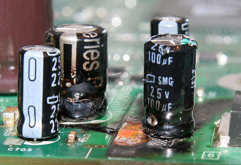
The lifespan of aluminum E-caps is finite, primarily limited by the gradual dry-out or evaporation of their internal liquid electrolyte. This phenomenon is described by the Arrhenius equation. This leads to the widely accepted “10°C rule”: the estimated service life of a wet aluminum E-cap approximately doubles for every 10°C reduction in its internal core temperature. PCB design must incorporate effective thermal management and derating strategies to ensure the actual operating temperature is well below the maximum rated value.
A key degradation phenomenon is the vicious cycle between ESR and lifespan: as the capacitor nears the end of its life, electrolyte dry-out causes the ESR to increase sharply. Under the same ripple current, higher ESR leads to greater internal heat generation, which in turn accelerates the dry-out rate of the remaining electrolyte.
Figure: Illustrative lifetime vs. temperature rules: wet Al electrolytics (~2× per −10 °C, Arrhenius-like) and device-specific polymer series (~10× per −20 °C; verify datasheets).
Relying solely on temperature derating is insufficient for predicting lifespan; the applied DC voltage also significantly impacts life. The precise wearout life (L) model (e.g., Cornell Dubilier's CDE model) accounts for the combined effects of temperature and voltage:
L = Lb × Mv × 2((Tm − Tc)/10)
Where Lb is the base life, Tm is the corresponding base temperature, and Tc is the actual core temperature. The voltage multiplier (Mv) quantifies the life extension from voltage derating:
Mv = 4.3 − 3.3 × (Va / Vr)
Va is the applied DC voltage, and Vr is the rated DC voltage. When Va < Vr, Mv > 1 indicates increased life. In engineering practice, by typically derating the applied voltage Va to the 50%–70% range of the rated voltage (per datasheet/industry standards), significant lifespan extension can be achieved, provided thermal and ripple requirements are met.
Figure: Practical voltage-derating starting points by capacitor class (device- and series-dependent; always verify with the datasheet and surge limits).
Aluminum electrolytic capacitors are not designed for frequent, rapid charge and discharge cycling, and are not suitable for high-frequency pulse energy storage. Frequent rapid cycling can cause internal overheating, excessive pressure, and dielectric damage.
To accurately evaluate the capacitor's equivalent model at the operating frequency, it is recommended to use an impedance analyzer or high-frequency LCR meter supporting up to 5 MHz to 10 MHz. For low-impedance, large-capacitance devices, the Series Equivalent Circuit Mode (SER/ESR) should be used for measurement;
Note: ESR ≠ |Z|; the impedance |Z| includes reactance and ESL, and engineering judgment should consider the phase angle or resonant point.
Good PCB layout is crucial for ensuring the performance of electrolytic capacitors is realized.
> Learn PCB Capabilities - NextPCB
The complexity of E-cap selection demands that the BOM precisely identifies the specific manufacturer and product series, not just the capacitance and voltage rating.
Leading global E-cap manufacturers, such as Nichicon, Nippon Chemi-Con, Rubycon, KEMET, and Vishay, have developed highly specialized product series for different applications.
Electronic Components at Competitive Prices | HQ Online
Storage Note: Aluminum E-caps can pass the manufacturer's specified shelf life (often equivalent to several years), but two main risks are reduced lead solderability and a temporary increase in leakage current. Thus, adhering to a 2–3 year storage limit and performing re-inspection upon expiry is advised; re-forming operations can restore leakage current figures, but other parameters that drift over time may not be fully recovered.
To seamlessly transition engineering design into mass production, the BOM must lock down the specific manufacturer, product series, and exact Manufacturer Part Number (MPN).
By leveraging NextPCB's One-Stop PCBA Manufacturing Service, your design can achieve closed-loop management from PCB fabrication, component procurement (BOM services), to SMT assembly:
Through the NextPCB platform, designers can seamlessly translate complex engineering selection results into mass-produced components.

References:
[1] Torki, J., Joubert, C., & Sari, A. (2023). Electrolytic capacitor: Properties and operation. Journal of Energy Storage, 58, 106330. https://doi.org/10.1016/j.est.2022.106330
[2] Bei You Han Shan. (2019, July 17). Structure, process, and failure modes of ceramic capacitors. Cnblogs. Retrieved from https://www.cnblogs.com/beiyhs/p/11200483.html
Still, need help? Contact Us: support@nextpcb.com
Need a PCB or PCBA quote? Quote now

