
 NextPCB Capabilities
Printed Circuit Boards
NextPCB Capabilities
Printed Circuit Boards
 PCB Assembly
 Layer Buildup
 SMD-Stencils
 PCB Design-Aid & Layout
 Mechanics
 Quality
 Drills & Throughplating
 Factory & Certificate
 PCB Assembly Factory Show
Certificate
PCB Assembly Factory Show
Certificate
Support Team
Feedback:
support@nextpcb.com


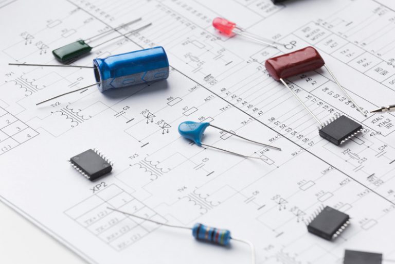
In electronics design and engineering, capacitors are essential components that significantly impact the functionality and quality of a Printed Circuit Board (PCB).
A PCB capacitor is a two-terminal electrical component that stores electric charges and enables the flow of alternating current (AC). Together with resistors and inductors, capacitors are fundamental passive components you can find in a wide variety of circuits. With all the components on a circuit board, it is second to resistors when it comes to numbers.
It is necessary to note that when we mention PCB capacitors in this article, we are referring to the Printed Circuit Board capacitors that are commonly used these days, not to be confused with PCB (Polychlorinated Biphenyls Capacitors), which has been prohibited in some countries.
The importance of capacitors and choosing the right ones cannot be overstated, as they are critical to the successful operation of a circuit board design. They are one of the key elements that can make or break a project; hence, selecting the right capacitor components for a PCB design is critical to ensure a successful circuit design.
In this article, we will outline the different types of capacitors that are common on PCBs, provide a guide on how to select the right capacitor for your project and explore the importance of handling capacitors safely. Hence, if you are looking for more information about PCB capacitors for your electronics project, this article is for you.
PCB capacitors are the basic and indispensable component of a printed circuit board. They are a type of passive component common in various circuits, functioning like a battery, but their ability to store electric charge is for only a brief period of time, and then they will be releasing it back to the circuitry whenever the circuit board requires the stored power. This is also to ensure that the flow of current in the circuitry is stable.
You can see PCB capacitors in a variety of electronic applications and devices, from computers and cell phones to audio equipment and medical devices. Their role cannot be underestimated, as these components help regulate voltage and protect the integrity of signal transmission, essential for preventing the build-up of electrical potential between electronic components, and providing a consistent supply of power to the device.
Different types of PCB capacitors have their own distinct features and uses in electronic design and can be classified according to the conductor or dielectric material used in the capacitor. This substance, plus two metal plates, are used to make capacitors.
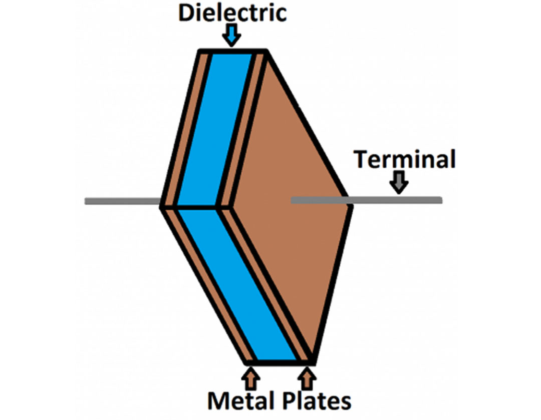
In order to prevent them from touching, the metal plates are arranged in parallel and put very close to one another. Because a capacitor features two metal objects with non-dielectric materials separating them, its behavior is the same whether it is a PCB capacitor or a conventional capacitor type. This combination of pads, PCB tracks, pins, and components form a capacitor.
Capacitors found on printed circuit boards or PCBs often serve two primary purposes. They are capable of storing electric charge and allowing alternating current to flow through them while preventing direct current from doing so. In addition, electricity is charged onto and discharged from PCB capacitors in the context of an electric field.
How exactly do they perform their functions? Capacitors require a charge to begin functioning properly. This component passes alternating current or AC but not direct current or DC. A capacitor receives an electric current, which remains in its first plate once it enters the capacitor.
You might wonder why it sits on the first plate. The reason that it stays there is due to the fact that the insulator does not let a negative charge in. The initial metal plate acquires a negative charge as a result of the accumulation of additional electrons within the plate.
This plate, which also acts as a barrier, moves the extra electrons in the capacitor to the opposite side. At this point, a positive charge will be applied to the second plate.
The charge is being built up on the two metal plates. On the other hand, the electrons with positive and negative charges will attempt to join forces; hence, they are separated from one another by an insulating substance which is also known as dielectric.
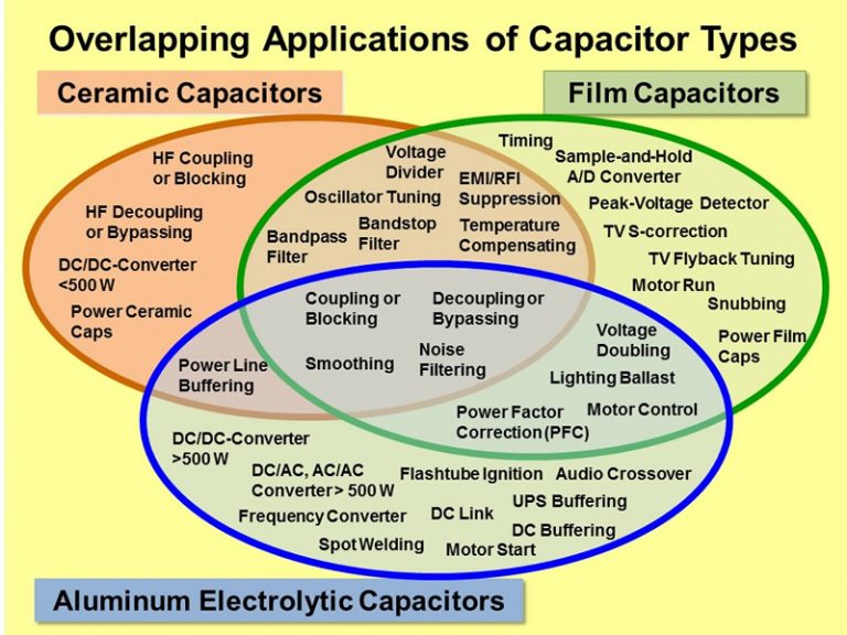
Capacitors have various applications in PCBs, which typically include the following:
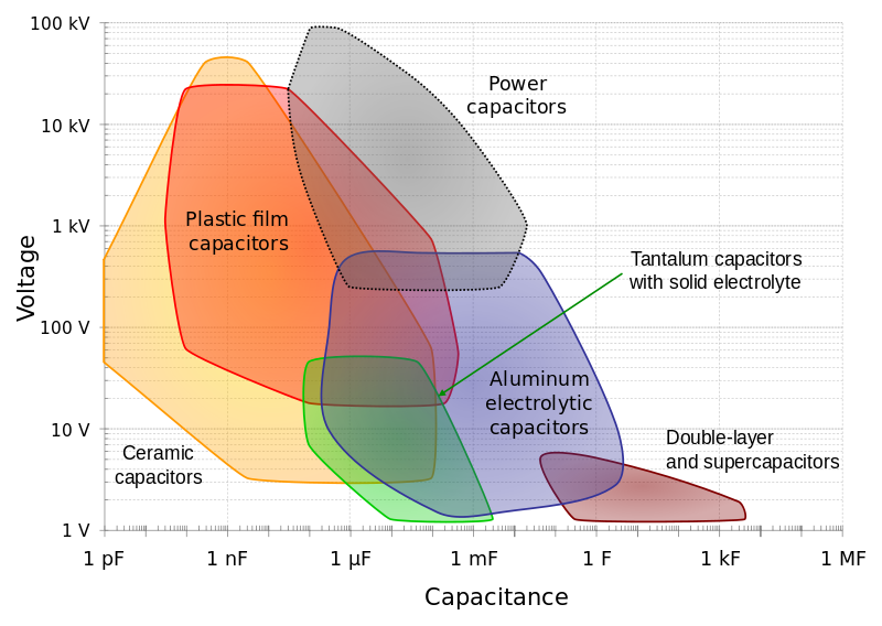
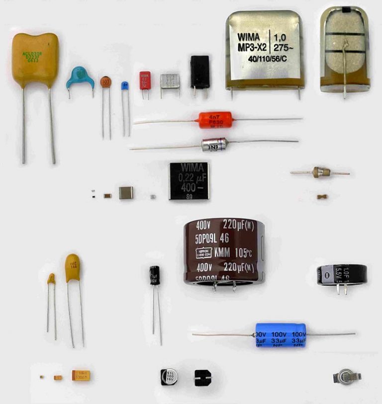
There are multiple types of capacitors available in the market today. Below are some of the popular ones on PCBs:
Capacitor Comparison
| Type | Aluminum Electrolytic Capacitor | Multilayer Ceramic Capacitor | Tantalum Capacitor | Film Capacitor |
|---|---|---|---|---|
| Dielectric | Aluminum Oxide | Several ceramics | Tantalum | Plastic film |
| WorkingVoltage | 4 to 400V | 6.3 to 250V | 2.5 to 50V | 50 to 1600V |
| Capacitance | 47 to 10000µF | 0.001 to 100µF | 0.47 to 1000µF | 0.001 to 10µF |
| Advantages | The wide array of breakdown voltages and capacitances |
|
Small package, Large, stable capacitance |
|
| disadvantages |
|
|
|
|
Aluminum electrolytic capacitors are common in different types of consumer electronics, like PCB assemblies and power supplies. These are utilized when a significant amount of capacitance is needed, and leakage current is not a major consideration. They are the most commonly used type of electrolytic capacitors.
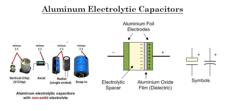
There are two types of Aluminum electrolytic capacitors, the etched foil type, and the plain foil type. These capacitors have extremely high capacitance values relative to their size because of the thickness of the aluminum oxide coating and the high breakdown voltage.
The permittivity and the surface area are increased when the aluminum oxide on the cathode and anode foils is chemically etched. Due to the etching process, the etched foil type is smaller in size than the plain foil type, but it won't be able to withstand high DC. The range of their capacitance values is 1uF up to 47,000uF, and the tolerance range is up to 20%.
Electrolytes have this feature to self-heal a damaged plate and re-anodize the foil sheet. Be mindful as these can let current pass from one plate to another, destroying the capacitor. This happens when you remove or detach the aluminum oxide coating.
For DC blocking, bypass circuits, and coupling, the etched foil types are mostly used. The plain foil type works best as flattening or smoothing capacitors in power supplies.
Different styles of Aluminum electrolytic capacitors:
Ceramic capacitors are one of the most common capacitors these days. Two types of ceramic capacitors that are popular are disc capacitors and multilayer ceramic capacitors or MLCC.

Ceramic disc capacitors are excellent for higher frequencies; they are unsuitable for bulk filtering because they become too large for higher capacitance values. A sizable electrolytic capacitor is typically connected in parallel with a ceramic disc capacitor in circuits where maintaining the stability of a voltage source is essential. While the electrolytic will perform most of the work, the little ceramic disc capacitor will filter out high frequencies that the large electrolytic capacitor will miss.
Currently, MLCC or multilayer ceramic capacitors are typical in circuits as the capacitance rating can even reach hundreds of microfarads or µF. With the multi-stacked and thin dielectric layers, high capacitance is achieved in order to make up for their smaller total plate area and noticeably thick layers. Ceramic capacitors use dielectric materials with a much greater dielectric constant.
Two of the most widely utilized dielectric materials for multilayer ceramic capacitors are titanium dioxide (r = 86-173) and barium titanate (r = 1250-10000), and each one is used to create a distinct class of capacitors.
The low capacitance ceramic capacitor days are gone. The tantalum or electrolytic capacitors are being replaced by modern ceramic capacitors now as the cost is less expensive but can still provide higher capabilities.
Tantalum capacitor is one of the electrolytic type capacitors. Its anode is made of tantalum metal, while the cathode can either be liquid or solid electrolyte and an oxide layer that serves as the dielectric. A very thin dielectric is made possible with the use of tantalum.
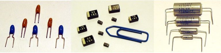
Tantalum "pearls", Tantalum chips, and Axial tantalum capacitors
Tantalum capacitors don't require the usage of aluminum-coated capacitor paper for firing, in contrast to conventional electrolytic capacitors that do so using electrolytes. It uses a thin tantalum pentoxide film coating on the tantalum metal surface.
Compared to ceramic disc capacitors, tantalum capacitors are smaller yet have a higher capacitance per unit of size. But unlike ceramic capacitors, electrolytic caps are polarized; therefore, installation must be precise and error-free to avoid blasting damage due to reversed polarity.
Although they are more expensive, these are common on the circuit boards of small electrical equipment due to their size and high capacitance.
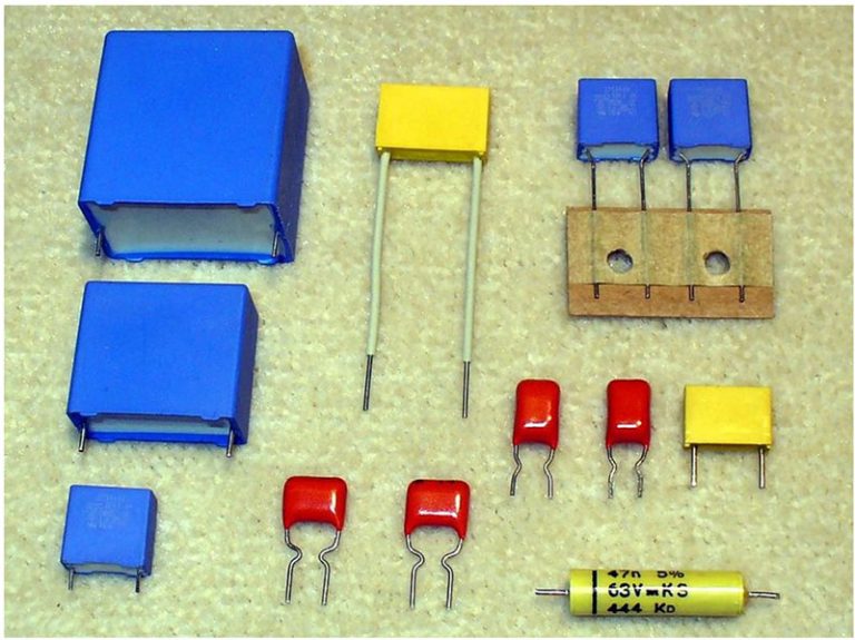
Film capacitors are versatile as there is a wide range and various types of the plastic film currently being used. Polymer film, plastic film, PTFE film, film dielectric, metalized film, power film, polystyrene film, or just film caps are some examples of insulating plastic film used as dielectric; hence, they are referred to as "film capacitors".
They are non-polarized types of capacitors employed in various applications, and the cost is typically less than that of the options above. The film may be metalized or left untreated after manufacture, depending on the needs of the capacitor.
Old paper capacitors were non-polar but featured a black ring on one end. According to the black band, the paper capacitor's end contained some visible metal foil (which acted as a shield). A ground connection was made at the end using the metal foil (or lowest voltage). The foil shield's primary goal was to extend the lifespan of the paper capacitor.
Printed circuit boards are ubiquitous in today's electronics industry, with capacitors playing an essential role in their proper functioning. In the case of printed circuit boards, capacitors maintain the stored charge, which allows the PCB to transmit data properly and regulate power.
However, their significant role in PCBs is more than just banking electrical energy. Below are just some of the many benefits of capacitors:
When considering the importance of capacitors on PCBs, you can see that they directly impact a product's overall functionality. Without capacitors, the electronic components of the PCB would not be able to work properly, thus severely limiting the PCB's capabilities. Hence, selecting the right capacitor for your project is vital.
Knowledge of the different properties and characteristics of each capacitor is of utmost importance when it comes to PCB design and assembly. You should consider the fundamentals during the planning stage. This is to avoid any lapses or miscalculations upon manufacturing.
The selection of a specific PCB capacitor heavily depends on the application requirements and overall circuit design. Different capacitors have different roles.
Careful consideration of capacitance, voltage rating, polarity, temperature coefficient, dielectric absorption, tolerance, and others must be taken into account to ensure optimal PCB capacitor selection.
There are several types of PCB capacitors available, each offering different characteristics and performance. You must take into account the application and function of the overall circuit design.
For instance, decoupling capacitors are crucial in high-frequency circuits to reduce noise and stabilize the power supply, while filtering capacitors eliminate unwanted frequencies.
To ensure optimal functionality and quality of your circuit design, it is crucial to carefully select PCB capacitors based on their specific application and parameters.
When choosing capacitors for PCB design, one of the critical parameters to consider is capacitance value. This value determines the amount of charge a capacitor can carry and release, and is measured in farads (F).
The required capacitance value depends on the specific application and circuit design. It is essential to select a capacitor with a capacitance value higher than the minimum required value.
A higher capacitance value can provide better performance and stability to the circuit. Moreover, adjusting the voltage level can increase or decrease the capacitor's charge, making it an even more critical parameter to consider.
The tolerance value is the deviation from the rated capacitance value, indicating how much its actual capacitance value can vary from the stated value on its datasheet. This difference can affect how well the capacitor meets the electrical requirements of the PCB.
Capacitors with a low tolerance are preferable for sensitive applications such as timing elements. However, coupling capacitors have a wide tolerance and can easily handle even the lowest frequencies. It can maintain its capacitance value despite variations in temperature, humidity, and other environmental factors.
Still, selecting a capacitor with a tolerance rating that is appropriate for the current requirements of your circuit design is of utmost importance.
It is vital to consider the dielectric permittivity of the capacitor material. Different materials of capacitors provide varying levels of insulation, which can affect the efficiency of the capacitor. Higher permittivity signifies greater capacitance, which means that the capacitor can store more charge. Dielectric materials such as ceramic and mica are common in capacitors, each with its own properties.
For instance, ceramic capacitors have a smaller charge capacity; however, they leak less current, making them ideal for applications requiring low leakage. On the other hand, Mica capacitors have a higher capacitance value due to their high permittivity and are suitable for high stability and precision applications.
The right dielectric material can significantly impact a capacitor's performance and the PCB design's overall functionality. It is essential to consider the application's specific requirements and the trade-offs between different dielectric materials before selecting a capacitor.
There is a bit of a challenge in selecting the right size of capacitor per project. Temperature, ripple, capacitance, current rating, voltage rating, and physical size are just a few of the factors to consider. The higher the capacitance value, the bigger the capacitor size becomes. The shape, width, height, and diameter must match the PCB design.
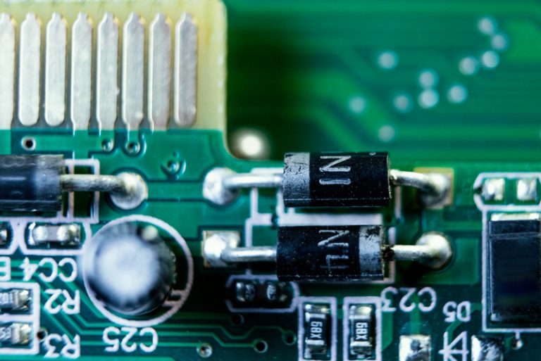
Under harsh environments, through-hole capacitors are the best option due to their reliability. These caps are soldered in the layers of the board to have a better mechanical bond. They are stronger in comparison to SMD (Surface Mount Device) capacitors.
The most popular through-hole capacitors in use are ceramic, film, aluminum electrolytic, and aluminum polymer capacitors. The alum polymer caps are chunkier and shorter, while the alum electrolytic caps are longer and narrower. Film caps have the widest footprint of 2.5cm long, while ceramic caps have a minimum of less than 5mm long.
If price is an issue, SMDs cost lower but with minimal parasitic inductance effect.
The highest voltage a capacitor can store safely and should be exposed to is indicated by its voltage rating, also known as working voltage.
The voltage rating of a capacitor should be higher than the expected peak voltage of the circuit it is powering. Hence, a device or any electronic equipment may malfunction and fail if the capacitor used is over the capacitance or maximum working voltage.
Polarized capacitors, also known as electrolytic capacitors, can only tolerate voltage in one polarity. Non-polarized capacitors, on the other hand, can tolerate voltage in either polarity.
The choice between polarized and non-polarized capacitors depends on a few factors, including the application and voltage requirements of your PCB design.
While polarized capacitors have higher capacitance values and are often used in power supplies, they also have a higher leakage current and can act as short circuits when used incorrectly. Non-polarized capacitors have lower capacitance values but are better suited for applications like AC coupling and bypassing.
Most capacitors are designed to withstand a certain temperature range, so you must select a capacitor with a temperature rating suitable for the environment in which your circuit is used. If the voltage or temperature rating exceeds, the capacitor can fail and cause damage to the board or other components.
It is important to consider the price of capacitors when purchasing components, as they can have a significant effect on the overall cost of the PCB.
For instance, electrolytic capacitors offer great accuracy, but it comes at a higher cost due to their lower tolerance rating and the need for a larger physical size to store the charge. Ceramic capacitors, on the other hand, are generally cheaper and have higher tolerance ratings. Therefore, you must consider the price vs. quality trade-off when selecting capacitors for your designs.
Choosing a capacitor with a wider tolerance might be a more cost-effective option, although it may compromise accuracy. Hence, understanding the balance between cost and performance is crucial in choosing the right capacitors for any PCB project.
These capacitors help to isolate local circuits from noise and power anomalies from other devices on shared power and ground.
The placement of a decoupling capacitor is critical, as it provides high transient currents to an IC to reduce power. Maintaining a low dynamic impedance from the individual IC supply voltage to the ground is crucial to minimize power supply noise coupling to the IC.
To follow good engineering practice, every IC should have at least one decoupling capacitor, and usually, a 0.1µF capacitor suffices. Multiple capacitors placed on the same supply pin should ensure that the smallest capacitor is closest to the IC and the rest of the capacitors follow in ascending order of capacitance.
Working with decoupling capacitors will benefit the voltage and reduce power noise coupling to the IC. Thus, it is essential to have a fundamental understanding of decoupling capacitors and how to incorporate them into your PCB design.
In addition, to avoid potential issues during PCB assembly, board masters utilize specific techniques such as designing footprints to ensure enough space for each part. By following these tips and best practices, PCB designers can choose the right capacitors for their design and avoid costly mistakes.
It is important for anyone designing and assembling PCBs to be familiar with the safe handling of these components as well as the potential hazards associated with them.
The following section provides a guide to the safe handling, storing, and disposing of PCB capacitors.

Electric shock: One hazard associated with PCB capacitors is the risk of electric shock. When they are used to store large amounts of voltage, they can build up a large amount of charge, which may result in electric shock (sometimes fatal if handled improperly. Before handling, care must be taken to ensure that they are properly discharged. It is, therefore, important to always use protective equipment when handling PCB capacitors, such as gloves and eye protection. Additionally, checking all connections and wiring before use is important to ensure no exposed wires are present.
Accidental fire: Another potential hazard with PCB capacitors is a fire risk. This can occur due to high electrical current passing through the capacitors. Therefore, it is important to ensure that the capacitors are intended for the job at hand, with appropriate power rating, and adequately cooled. Additionally, it is important to ensure that the capacitors are connected properly and that any exposed wiring is insulated. Improper connections can lead to a circuit malfunction or, worst case, a fire hazard. If possible, use a multimeter to test all connections before powering the device. It is also crucial to avoid overloading the capacitors. Excessive current or voltage can cause the capacitors to become damaged or even explode, creating a potentially dangerous situation.
Hazardous materials: Lastly, there is the risk of exposure to hazardous materials. Capacitors may contain hazardous chemicals to humans and the environment, so it is important to take proper precautions when handling these components. It is, therefore, important to wear appropriate protective gear when handling PCB capacitors.
Since PCB capacitors are sensitive to temperature and humidity, they must be stored in a temperature-controlled environment. Exposure to moisture and extreme temperatures can damage the capacitors and reduce their performance.
It's also important to keep the capacitors away from any magnetic fields, as these can interfere with the capacitors' electrical charge. They must be stored in EMI/RFI shielding bags when not in use to protect them from physical damage.
Ensuring proper labeling of the component is an important safety measure. This allows users to identify the component on the board and its characteristics easily.
Additionally, components should not be handled by hand during transit or storage; use local regulatory-approved containers for this purpose.
When disposing of PCB capacitors, consider whether the capacitor is rechargeable. Rechargeable capacitors can be recycled and taken to an appropriate waste management facility. If not, the capacitor must be securely packed and correctly labeled for disposal in line with local regulations.
Capacitors play a significant role on printed circuit boards. They impact the functionality and quality of a circuit. Hence, its importance can't be understated. While their presence is often taken for granted, capacitors play a crucial role in ensuring electrical circuits function properly.
Not only do capacitors serve a critical role in ensuring the functionality and quality of printed circuit boards, but there are also many types to choose from that offer various benefits and disadvantages.
When working with capacitors and circuit design, it is crucial to understand the impact each capacitor type will have on the project and the implications of tolerance and price variations when selecting the right capacitor for your PCB design. Evidently, optimizing a PCB and positioning electronic components is always a delicate and demanding activity.
In addition, the safe handling of PCB capacitors needs to be prioritized in order to avoid any potential hazards. To minimize the risks, careful labeling and disposal process, along with the use of protective gear and proper storage, is paramount to ensure safety at every step of production.
Ultimately, when thoroughly planned and used effectively, PCB capacitors are an invaluable component of successful PCB design.
Still, need help? Contact Us: support@nextpcb.com
Need a PCB or PCBA quote? Quote now


 Surface

