
 Surface


Lolly Zheng- Sales Account Manager at NextPCB.com

 NextPCB Capabilities
Printed Circuit Boards
NextPCB Capabilities
Printed Circuit Boards
 PCB Assembly
 Layer Buildup
 SMD-Stencils
 PCB Design-Aid & Layout
 Mechanics
 Quality
 Drills & Throughplating
 Factory & Certificate
 PCB Assembly Factory Show
Certificate
PCB Assembly Factory Show
Certificate
Support Team
Feedback:
support@nextpcb.com


Table of Contents
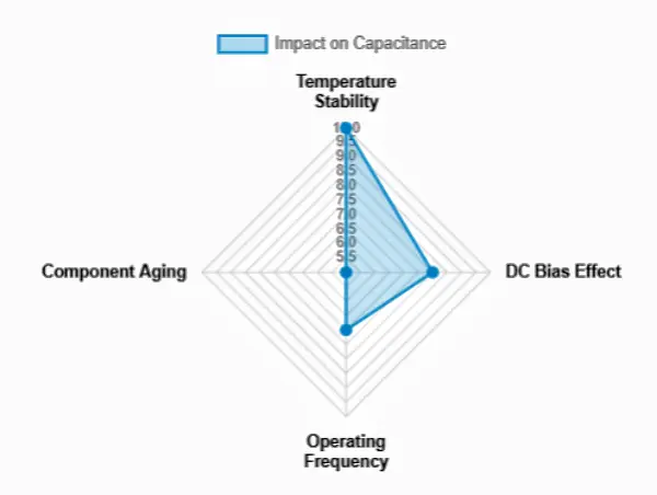
A ceramic capacitor uses ceramic material as its dielectric. It typically consists of two or more alternating layers of ceramic and metal, with the metal layers acting as electrodes. While they are often defined as having a “fixed value,” from an engineering perspective, it is crucial to understand that their effective capacitance is not absolutely constant; it is significantly influenced by external factors such as temperature, DC bias voltage, and operating frequency.
Thanks to ceramic materials' excellent insulating properties and adjustable dielectric constant, these capacitors excel in bypass, decoupling, filtering, and high-frequency applications. Their low Equivalent Series Inductance (ESL) and low Equivalent Series Resistance (ESR) make them indispensable in high-current and high-speed digital circuits.
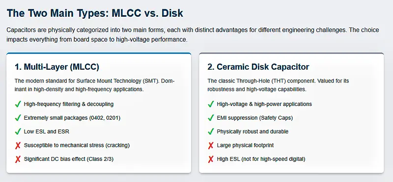
Physically, ceramic capacitors primarily come in two forms, each dominating different application areas:
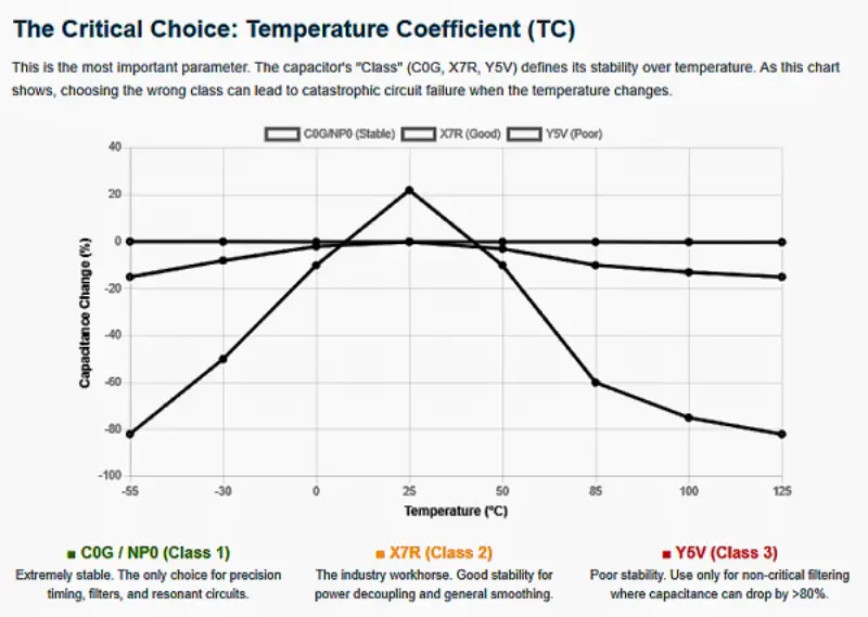
Selecting a capacitor is about more than just its capacitance value. For engineers, understanding the capacitor temperature coefficient is crucial. This coefficient defines how stable the capacitance value is as the ambient temperature changes.
Ceramic capacitors are categorized into different classes based on the ceramic dielectric material used, which determines their stability and volumetric efficiency:
| Characteristic | Class 1 (e.g., C0G/NP0) | Class 2 (e.g., X7R) | Class 3 (e.g., Y5V) |
|---|---|---|---|
| Stability | Extremely High. Virtually no drift across the full temperature range. | Good Stability. Maintains performance within a defined range (-55°C to +125°C). | Poor Stability. Highly sensitive to temperature changes; generally unsuitable for precision circuits. |
| Applications | Resonant circuits, high-frequency filters, precision timing | IC power decoupling, general signal smoothing | General-purpose filtering where capacity accuracy is not critical |
| Capacitance Range | Smaller (pF to nF) | Medium (nF to µF) | Larger (up to 100µF and above) |
| Temp. Coefficient | ±30 ppm/°C | ±15% (Non-linear change) | +22% / -82% (Significant drift) |
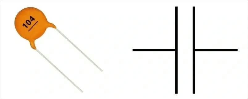
For through-hole or larger MLCCs, the component surface usually features printed codes. These ceramic cap codes often confuse beginners, but they adhere to strict industrial standards (EIA).
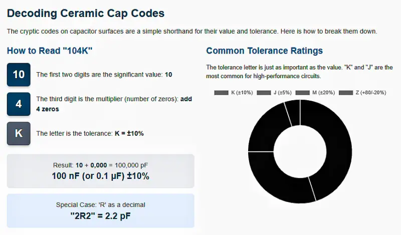
1. The Fundamental Three-Digit Rule
The most common encoding consists of three digits:
2. Engineering Example: Identifying "104"
Suppose your BOM calls for a 100nf ceramic capacitor, and the component you are examining is marked "104."
3. Quick Reference Table for Common Codes
| Code | Calculated Value (pF) | Common Value (nF/µF) | Typical Application |
|---|---|---|---|
| 102 | 1,000 pF | 1 nF | Signal Filtering |
| 103 | 10,000 pF | 10 nF | Noise Suppression |
| 104 | 100,000 pF | 100 nF (0.1 µF) | IC Power Decoupling (Standard) |
| 105 | 1,000,000 pF | 1 µF | Bulk Decoupling |
| 220 | 22 pF | - | Crystal Oscillator Load Cap |
Suffix Letters: Tolerance Rating
Special Case: Values Less Than 10pF
When designing a PCB, engineers must not only calculate parameters but also consider Design for Manufacturability (DFM). Ceramic capacitors, especially MLCCs, have a brittle ceramic body, making them highly susceptible to mechanical stress.
Failure Risk: When a PCB is subjected to bending, vibration, or excessive stress, the MLCC body can crack. This internal crack is a critical failure mode: it can cause electrode misalignment, leading to a short circuit (the most dangerous and common failure), increased leakage current, or in severe cases, an open circuit.
Layout Advice: Avoid placing large MLCCs near connectors, screw holes, or V-cut separation lines. These areas bear the maximum mechanical stress (bending moment) during assembly or separation, significantly increasing the risk of capacitor damage. If placement is unavoidable, adjust the capacitor's orientation so its long axis runs parallel to the direction of the expected mechanical stress.
After the design is finalized, the real challenge is transforming the design files into reliable physical hardware. For engineers, solving component "availability" is just as critical as solving circuit problems.
> Recommend reading: What Is Component Sourcing? A Complete Guide for PCB Designers & Manufacturers
In this phase, NextPCB collaborates closely with HQ Online (a prominent electronic component distributor based in Shenzhen, the Silicon Valley of Hardware), both operating under the HQ Electronics umbrella. This deep resource integration model is specifically designed to solve manufacturing pain points:
Keep Reading:
> PCB Capacitors: Why Is It Important and How to Choose?
> Capacitor Symbols: A Guide to Understanding the Different Types
Whether it's a ceramic disk capacitor used for suppressing power noise or a precision MLCC for high-frequency signal paths, the ceramic capacitor is a cornerstone of the electronic world. Mastering the reading of ceramic cap codes and the rules for selecting the correct capacitor temperature coefficient will make your circuit designs more robust.
On the path of hardware development, solid foundational knowledge combined with reliable manufacturing and supply chain support (such as the one-stop PCB and BOM service provided by NextPCB) is the key to successful project execution.
Note: This article aims to disseminate fundamental electronic component knowledge. For separate component search or purchase, please refer to professional distribution platforms like HQ Online; for comprehensive PCBA services including PCB manufacturing and BOM matching, NextPCB provides the necessary engineering support.

Still, need help? Contact Us: support@nextpcb.com
Need a PCB or PCBA quote? Quote now

