NextPCB Capabilities
 PCB Assembly
 Layer Buildup
 SMD-Stencils
 PCB Design-Aid & Layout
 Mechanics
 Quality
 Drills & Throughplating
 Factory & Certificate



Feedback determines whether a circuit becomes a more stable amplifier or a self-sustaining oscillator, depending on its sign and phase. This companion guide to Electronic Devices and Circuits and Transistor Biasing and Amplifier Design covers negative feedback topologies, the Barkhausen criterion, the most common RC, LC, and crystal oscillator circuits, and the PCB layout details that determine whether an oscillator actually runs at its designed frequency.
1. What Is Feedback in an Electronic Circuit?
Feedback means routing a portion of a circuit’s output back to its input. Whether that feedback opposes the input (negative feedback) or reinforces it (positive feedback) determines whether the resulting circuit behaves as a more stable, predictable amplifier or as a self-sustaining oscillator.
2. Negative Feedback: Types and Benefits
Negative feedback amplifiers are classified by two choices: whether the feedback network samples the output voltage or current, and whether it feeds that signal back in series or shunt (parallel) with the input.
| Topology | Samples | Feeds Back | Effect on Input/Output Impedance |
|---|---|---|---|
| Voltage-series | Output voltage | In series with input | Input impedance increases, output impedance decreases |
| Voltage-shunt | Output voltage | In shunt with input | Both input and output impedance decrease |
| Current-series | Output current | In series with input | Both input and output impedance increase |
| Current-shunt | Output current | In shunt with input | Input impedance decreases, output impedance increases |
Regardless of topology, negative feedback trades away some open-loop gain in exchange for several practical benefits: the closed-loop gain becomes far less sensitive to component and transistor-to-transistor variation, bandwidth extends roughly in proportion to the amount of gain given up (the gain-bandwidth product stays constant), nonlinear distortion is reduced, and input/output impedance can be deliberately shifted toward whatever a following or preceding stage needs.
3. Positive Feedback and the Barkhausen Criterion
An oscillator is, in effect, an amplifier that generates its own input through positive feedback. For sustained, stable oscillation, the Barkhausen criterion must be satisfied at the desired frequency: the magnitude of the loop gain (amplifier gain A multiplied by feedback factor β) must equal exactly 1, and the total phase shift around the loop must equal 0° (or an integer multiple of 360°). If loop gain is less than 1, oscillations die out; if it starts above 1, oscillations grow until amplifier nonlinearity naturally limits the amplitude back toward the criterion.
4. RC Oscillators
RC Phase-Shift Oscillator
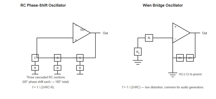
Three cascaded RC sections, each contributing 60° of phase shift, combine to produce the full 180° needed to turn an inverting amplifier’s output back into an in-phase signal at its input (180° from the amplifier plus 180° from the RC network equals the 360° required by the Barkhausen criterion). For equal-value RC sections, oscillation frequency is approximately f = 1 / (2πRC√6).
Wien Bridge Oscillator
A Wien bridge oscillator uses a series RC and parallel RC network arranged in a bridge configuration as the feedback path, driving a non-inverting amplifier. Oscillation frequency is approximately f = 1 / (2πRC). Its low distortion and simple gain-stabilization requirements make it a common choice for audio-frequency signal generators.
5. LC Oscillators
Hartley Oscillator
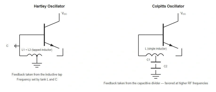
A Hartley oscillator uses a tapped inductor (or two separate inductors) together with a single capacitor as the resonant tank; feedback is taken from the inductive tap. Oscillation frequency is set by the tank’s effective inductance and capacitance, following the standard LC resonance relationship.
Colpitts Oscillator
A Colpitts oscillator uses the mirror-image approach: a tapped capacitor pair (two capacitors in series) together with a single inductor forms the tank, and feedback is taken from the capacitive divider. Because capacitors generally hold their value more precisely than tapped inductors at high frequency, Colpitts oscillators are typically favored over Hartley oscillators for higher-frequency and more frequency-stable RF applications.
6. Crystal Oscillators
A quartz crystal exhibits the piezoelectric effect and behaves electrically as an extremely high-Q resonant circuit, resonating at a very precise, temperature-stable frequency set by its physical cut and dimensions. Replacing an LC tank with a crystal — commonly in a Pierce oscillator topology — produces frequency stability that ordinary LC oscillators cannot match, which is why crystal oscillators are the standard choice for clock generation and RF frequency references.
7. Oscillator Types Compared
| Oscillator Type | Typical Frequency Range | Frequency Stability | Common Use |
|---|---|---|---|
| RC (phase-shift / Wien bridge) | Audio range (Hz to tens of kHz) | Moderate | Audio signal generators |
| LC (Hartley / Colpitts) | RF range (hundreds of kHz to hundreds of MHz) | Good | RF transmitters, receivers, local oscillators |
| Crystal | Fixed, precise (kHz to hundreds of MHz depending on cut) | Very high | Clock generation, timing references |
8. From Oscillator Theory to PCB Layout
Oscillator frequency and stability are especially sensitive to layout, more so than most other analog circuits:
- Parasitic capacitance in LC tanks: every trace and pad adds a small amount of stray capacitance directly into the tank circuit, which shifts the actual oscillation frequency away from the calculated value — keeping tank components tightly grouped with short traces minimizes this drift.
- Crystal placement: crystal oscillator circuits should keep the crystal and its load capacitors as close as possible to the driving IC or transistor pins, with a guard ring or ground pour around the crystal traces to reduce parasitic coupling and support reliable startup.
- Isolation from switching noise: oscillator sections benefit from a separate, quiet ground zone away from digital switching or power-conversion circuitry elsewhere on the board, which can otherwise couple noise into the feedback path and cause frequency jitter.
A DFM check before prototyping can flag clearance and grounding issues around sensitive oscillator sections early. For broader layout practices, see our PCB Design Layout guide.
Frequently Asked Questions
What is the Barkhausen criterion?
The Barkhausen criterion states that for a circuit to sustain oscillation, the loop gain magnitude must equal 1 and the total phase shift around the feedback loop must equal 0° (or a multiple of 360°) at the oscillation frequency.
What is the difference between a Hartley and a Colpitts oscillator?
A Hartley oscillator uses a tapped inductor with a single capacitor to form its resonant tank, while a Colpitts oscillator uses a tapped capacitor pair with a single inductor. Colpitts oscillators are generally preferred at higher frequencies due to better component stability.
Why are crystal oscillators more stable than LC oscillators?
A quartz crystal has a much higher Q factor and a more temperature-stable resonant frequency than an LC tank circuit, which is made from discrete inductors and capacitors that are more sensitive to component tolerance, temperature, and parasitic effects.
What is the difference between positive and negative feedback in electronics?
Negative feedback opposes the input signal, improving gain stability, bandwidth, and distortion at the cost of raw gain. Positive feedback reinforces the input signal and, when it satisfies the Barkhausen criterion, causes the circuit to oscillate rather than simply amplify.
9. Conclusion
Feedback is the hinge on which an amplifier and an oscillator both turn: the same building blocks — a biased transistor and a passive feedback network — produce a stable, low-distortion amplifier under negative feedback, or a self-sustaining signal source under positive feedback that satisfies the Barkhausen criterion. As with the amplifier and device fundamentals covered in our Electronic Devices and Circuits and Transistor Biasing and Amplifier Design guides, getting the theory right is only half the job — oscillator circuits in particular live or die on PCB layout details that never show up in the schematic.
Ready to Build a Stable Oscillator or Amplifier Circuit?
Get an instant PCB quote, run a free DFM check on your layout, or order a PCB prototype to verify oscillator frequency and stability before full production.