
 Surface


Arya Li, Project Manager at NextPCB.com

 NextPCB Capabilities
Printed Circuit Boards
NextPCB Capabilities
Printed Circuit Boards
 PCB Assembly
 Layer Buildup
 SMD-Stencils
 PCB Design-Aid & Layout
 Mechanics
 Quality
 Drills & Throughplating
 Factory & Certificate
 PCB Assembly Factory Show
Certificate
PCB Assembly Factory Show
Certificate
Support Team
Feedback:
support@nextpcb.com


Table of Contents
The right PCB substrate matches three constraints simultaneously: thermal operating range, signal frequency, and unit cost target.
For most designs running below 1 GHz with a peak board temperature under 130°C, standard FR-4 (Tg 130–140°C) is sufficient. Upgrade to High-Tg FR-4 (Tg 170°C+) when reflow cycles exceed two passes or ambient temperatures stay above 130°C. Switch to Rogers or PTFE laminates when operating frequencies exceed 6 GHz or insertion loss budgets are tighter than −1 dB/inch. Choose aluminum-backed MCPCB when thermal resistance matters more than routing complexity.
Everything else is a trade-off between those four options.
| Substrate Type | Tg (°C) | Dk @ 1 GHz | Df @ 1 GHz | Thermal Conductivity (W/m·K) | Relative Material Cost | Primary Use Case |
|---|---|---|---|---|---|---|
| Standard FR-4 | 130–140 | 4.2–4.5 | 0.018–0.022 | ~0.25 | 1× (baseline) | Consumer electronics, IoT, general-purpose |
| High-Tg FR-4 (e.g., Shengyi S1000-2) | 170–180 | 4.0–4.4 | 0.016–0.020 | ~0.30 | 1.3–1.8× | Automotive ECU, industrial power, multi-reflow assemblies |
| Halogen-Free FR-4 | 150–170 | 3.8–4.2 | 0.012–0.018 | ~0.30 | 1.4–2.0× | RoHS-critical products, high-humidity environments |
| Rogers 4003C | 280+ | 3.55 ±0.05 | 0.0027 | ~0.64 | 8–12× | RF/microwave, 5G antennas, radar modules |
| PTFE (e.g., Rogers RT/duroid) | 73–100 | 2.2–2.94 | 0.0009–0.002 | ~0.24 | 15–25× | mmWave, aerospace, high-power RF |
| Aluminum MCPCB | N/A | N/A | N/A | 1.0–4.0 | 2–4× | High-power LED, motor drivers, power modules |
| Polyimide (Flex PCB) | 360–410 | 3.2–3.5 | 0.003–0.008 | ~0.16 | 3–6× | Wearables, medical devices, dynamic-flex applications |
How to use this table: Identify your maximum operating temperature first (→ Tg column), then check frequency (→ Dk/Df columns), then validate against budget (→ Cost column).
FR-4 epoxy-fiberglass laminate covers roughly 70–80% of PCB production volume globally. The flame-retardancy grade runs from FR-1 to FR-5; FR-4 occupies the practical center of that scale — adequate fire resistance at a manufacturing cost that keeps BoM targets realistic.
When standard FR-4 works:
When FR-4 fails:
Practical threshold: If your thermal cycling qualification profile requires more than 500 cycles between −40°C and +125°C, move to High-Tg FR-4 as a minimum.
High-Tg FR-4 raises the glass transition temperature to 170–180°C (some formulations reach 200°C) by modifying the epoxy resin system — typically introducing multifunctional epoxy or bismaleimide triazine (BT) blends.
What this buys you:
What it costs you:
Recommended materials in this category:
NextPCB stocks Shengyi and Kingboard High-Tg laminates as standard options, enabling same-spec reorders without material qualification restarts.
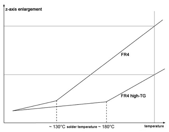
The Coefficient of Thermal Expansion (CTE) describes how much a material expands per degree Celsius of temperature change. For PCBs, the critical axis is Z (through-board), because copper via barrels expand much less than FR-4 resin under heat.
| CTE Region | Condition | FR-4 Z-axis CTE (typical) |
|---|---|---|
| Alpha 1 (α1) | Below Tg | 50–70 ppm/°C |
| Alpha 2 (α2) | Above Tg | 200–300 ppm/°C |
The Alpha 2 value is the one that causes via cracking in field failures. Standard FR-4 spends a significant portion of every reflow cycle in the Alpha 2 region. Reducing resin content in the laminate stack-up or using low-CTE resin systems brings Alpha 2 down — but these modifications reduce dielectric isolation and can affect CAF (conductive anodic filament) resistance. Stackup engineers must balance these trade-offs in the design phase, not after layout is complete.
Design rule of thumb: For boards with through-hole vias in 4+ layer stacks, request Z-axis CTE data from your laminate datasheet. If Alpha 2 exceeds 250 ppm/°C, add thermal via tenting or switch to High-Tg material before sign-off.
For 2.4 GHz Wi-Fi and Bluetooth antenna traces, high-performance FR-4 variants — specifically those with tightly controlled Dk (e.g., Isola IS410, Dk = 4.0 ±0.15 at 1 GHz) — can meet impedance targets with careful stackup design and controlled-impedance manufacturing. The key is specifying actual measured Dk at your operating frequency, not nominal room-temperature values.
Above 6 GHz, FR-4’s Df (dissipation factor) of ~0.020 introduces insertion loss that exceeds most link budgets. Rogers 4003C’s Df of 0.0027 represents roughly an 8× improvement — the difference between a functional 10 GHz radar front-end and one that fails link margin at temperature extremes.
Decision criteria for RF substrate upgrade:
NextPCB supports Rogers material orders with DFM review included, confirming trace width and copper weight against your target impedance before production begins.
This is one of the most frequently debated substrate decisions in power electronics and LED driver design.
| Design Criteria | Aluminum MCPCB | FR-4 + Thermal Vias + 2 oz Cu |
|---|---|---|
| Thermal resistance (typical) | 0.5–1.5°C/W | 3–8°C/W |
| Double-sided routing | Not practical | Fully supported |
| Through-hole vias | Not supported | Fully supported |
| Layer count | 1–2 layers max | 2–16 layers |
| Relative cost (same area) | 2–4× FR-4 | 1.2–1.8× FR-4 |
| Best for | >3W per LED, compact form factor | Complex driver topology with moderate thermal load |
Recommendation: If your LED module dissipates more than 3W in a space smaller than 30×30 mm, MCPCB reduces junction temperature enough to justify the cost. For LED controllers or motor drivers where routing complexity demands multi-layer design, FR-4 with a thermal via array (0.3 mm vias, 0.6 mm pitch, under pad) is the cost-effective path.
| Property | Polyimide (PI) | Polyester (PET) |
|---|---|---|
| Maximum continuous temp | 260°C | 105–120°C |
| Solderable | Yes | No (cold-bonded only) |
| Flex cycles (dynamic) | 100,000+ | 10,000–50,000 |
| Moisture absorption | ~2.5–3% | ~0.4% |
| Relative cost | 1× | 0.4–0.6× |
PI is the default choice for any flex circuit that goes through reflow soldering or experiences repeated dynamic bending (e.g., hinge mechanisms, wearable sensors). PET is appropriate for membrane switch overlays and static-flex ribbon cables where the PCB will never be soldered and deflects only a few times across product lifetime.
Halogen-free (HF) materials substitute phosphorus and nitrogen-based flame retardants for the bromine compounds used in standard FR-4. The engineering benefits beyond RoHS compliance:
Trade-off to understand: HF laminates have lower peel strength at high temperatures compared to standard FR-4 and require tighter process control during lamination. Confirm your PCB manufacturer’s process qualification for the specific HF laminate specified.
START: What is your maximum board temperature during operation or assembly?

├── < 130°C continuously, ≤ 2 reflow passes
│   ├── Frequency < 2 GHz → Standard FR-4
│   └── Frequency 2–6 GHz → High-performance FR-4 (controlled Dk)
│
├── 130–170°C or > 2 reflow passes
│   ├── No RF requirement → High-Tg FR-4 (Tg 170°C)
│   └── RF 2–6 GHz → High-Tg + Controlled-impedance stack-up
│
├── > 6 GHz or Df-sensitive signal chain
│   └── Rogers 4003C / 4350B, or PTFE-based laminate
│
├── Primary constraint is thermal dissipation (power electronics, LEDs)
│   ├── > 3W/component, single/double layer → Aluminum MCPCB
│   └── Complex routing, moderate thermal load → FR-4 + thermal vias
│
└── Flexible / dynamic-bend requirement
    ├── Soldering required or > 50,000 flex cycles → Polyimide (PI)
    └── Cold-bond only, static flex → PET (cost-optimized)
Selecting the right substrate is a critical decision that directly impacts your PCB's performance, thermal management, and long-term reliability. We have summarized the most debated topics from engineering communities like Reddit to help you make an informed choice.
Q1: When must I move from standard FR-4 to High-Tg material?
When continuous operating temperature exceeds 130°C, or when the assembly process involves more than two lead-free reflow passes. High-Tg materials (Tg 170°C+) maintain dimensional stability and prevent via-barrel cracking under repeated high-temperature excursions. Key application segments: automotive ECU boards, industrial power supplies, high-current LED controllers.
Q2: Can FR-4 handle 2.4 GHz or 5 GHz RF?
For Wi-Fi and Bluetooth antenna feeds with controlled impedance, high-consistency FR-4 variants (e.g., IT-180A) can meet performance requirements when Dk is measured at operating frequency and specified in the stackup. For 10 GHz+ or insertion loss specs below −0.5 dB/inch, Rogers or PTFE laminates are required. The key differentiator is Df: FR-4 Df ≈ 0.020; Rogers 4003C Df = 0.0027.
Q3: Does Dk variation affect impedance control on my PCB?
Yes. FR-4 Dk shifts with frequency and moisture content, causing controlled-impedance traces to deviate from target values. For high-speed designs (DDR4, PCIe Gen 3+), request measured Dk at your signal frequency from the laminate datasheet and input that value into your stackup simulation before releasing for manufacturing. NextPCB’s engineering team can provide stackup impedance verification at the DFM stage.
Q4: What is the practical difference between Shengyi and standard FR-4?
Shengyi laminates (e.g., S1000-2, S1170) are produced under tighter thickness tolerance, more consistent Dk uniformity across the panel, and better resin distribution in the weave. For standard consumer applications, the difference is marginal. For impedance-controlled multi-layer designs or High-Tg requirements, the tighter specs reduce manufacturing variance and improve first-pass yield.
Q5: Why are halogen-free materials recommended for high-layer-count boards in humid environments?
Halogen-free laminates typically have lower moisture absorption than standard FR-4. This matters because absorbed moisture raises the effective Dk of the laminate, shifting controlled-impedance values and increasing signal loss. In outdoor, automotive, or marine applications where the board sees humidity cycling, halogen-free material improves long-term electrical stability.
NextPCB supports substrate selection at the DFM review stage, before production begins. Key capabilities relevant to this decision:
Substrate selection questions specific to your design can be submitted with your Gerber files during the quote stage. The engineering review flags material compatibility issues before tooling begins.
Substrate material selection is a constraint-matching problem, not a default choice. Match Tg to your thermal profile, Dk/Df to your signal frequency, and CTE to your via structure before committing to a laminate. Standard FR-4 remains the right answer for the majority of designs. Upgrading costs real money — but choosing the wrong substrate costs more in field failures, rework, and yield loss.
Use the comparison table and decision tree in this guide as a starting checklist, then validate your specific parameters with your PCB manufacturer’s stackup data before layout sign-off.

Still, need help? Contact Us: support@nextpcb.com
Need a PCB or PCBA quote? Quote now

