
 NextPCB Capabilities
Printed Circuit Boards
NextPCB Capabilities
Printed Circuit Boards
 PCB Assembly
 Layer Buildup
 SMD-Stencils
 PCB Design-Aid & Layout
 Mechanics
 Quality
 Drills & Throughplating
 Factory & Certificate
 PCB Assembly Factory Show
Certificate
PCB Assembly Factory Show
Certificate
Support Team
Feedback:
support@nextpcb.com


Introduction
PCBs rise with silicon semiconductors' development due to the emergence of modern technologies in the contemporary world. When considering PCBs, the diodes, resistors, inductors, and capacitors play a significant role in developing the PCBs for the different requirements. The diodes in the PCBs identifies as the main component in controlling voltage signals which allows current to flow in one direction and blocks it in the opposite direction according to the user requirements.
In this article, we will cover the following topics:
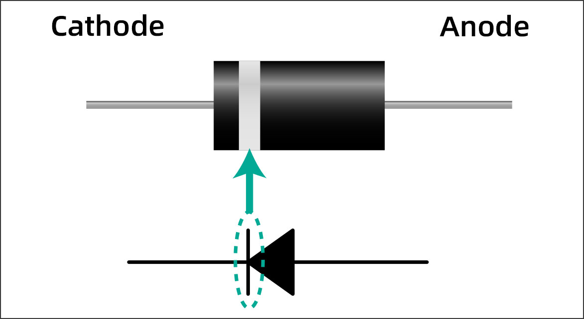
A PCB diode is a semiconductor device that allows current to flow in only one direction. It is made of semiconductor material, such as silicon, and has two terminals, called the anode and the cathode. The anode is the positive terminal, and the cathode is the negative terminal.
When a positive voltage is applied to the anode and a negative voltage is applied to the cathode, current will flow through the diode. However, if the polarity of the voltage is reversed, no current will flow. This is because the diode has a built-in electric field that prevents current from flowing in the opposite direction.
Since the above figure represents the physical view of the diode, electronic engineers and related professionals use an internationally accepted symbol to represent the PCB diodes. So, with a standard diagram for the diode, all the enthusiastic electronic people will be able to identify the PCB diodes and the process of the PCB according to the diode assembling patterns.
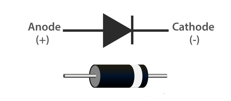
The above figure illustrates the diode symbol used when the electronic circuit is designed. As a result of having a common internationally accepted symbol for the PCB diodes, the simulation software in the electronics domain uses this symbol in their software.
According to the above figure, the symbolic illustration of the diode will be used to identify the process of the diode in a PCB. Moreover, the symbol will represent the direction of the current flow through the related diode-connected components. Since this is the main symbol for the diode, the symbol gets changed according to the other available functioning diodes.
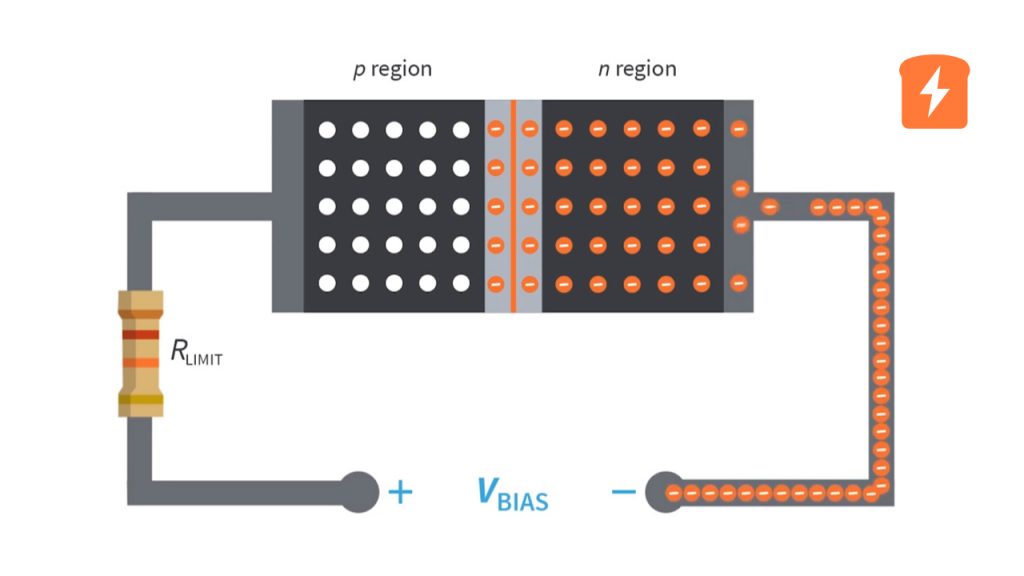
The main function of PCB diodes in the industry is as follows. A diode works based on the PN junction's unidirectional conductivity. The PN junction is transformed into a diode.
The interplay between the P and N junctions determines how a diode functions. The electrons will flow towards P in a typical scenario where P has a high number of holes and a small number of free electrons, and N has a lower density of holes and a greater density of free electrons, allowing the current to pass through P alone. This is the usual process that takes place when the circuit board diode is functioning.
This would happen if the voltage were gradually increased from zero while connecting the positive terminal of a source to the P junction and the source's negative end to the diode's N junction.
The potential barrier will prevent any current from flowing through initially.
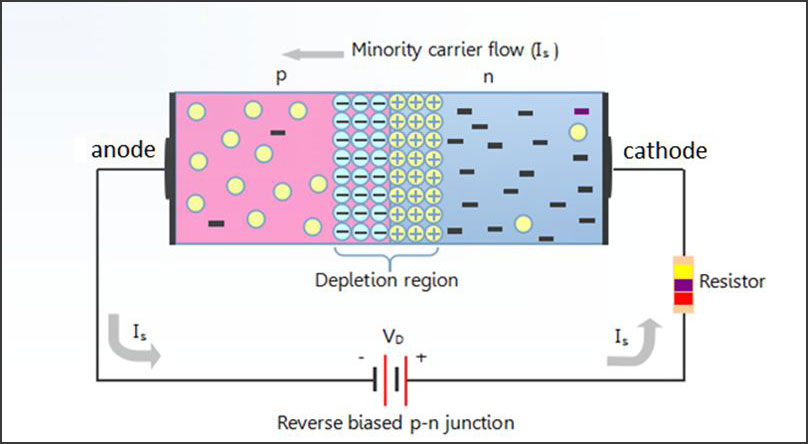
This would happen when the voltage source is linked to both the positive terminal of the N junction and the negative terminal of the P junction. In contrast to the forward-biased diode, this produces the opposite effect. The electrostatic attraction would cause the P junction holes to move farther away from the depletion region, exposing additional negative ions. When this happens, the circuit will get closed off, and no electricity will be able to pass through it.
LEDs are arguably the most well-known modern use for diodes. These use a unique doping type, producing light when an electron passes through an n-p junction and emits a photon. This is the case because LEDs illuminate when a positive voltage is present. Any light frequency (color) can be emitted by changing the doping type from infrared to ultraviolet.
The conversion of AC electricity to DC using diodes is the most widespread. Diodes can be used to build various rectifier circuit types, the most fundamental of which are full wave center tapped, half wave, and full bridge rectifiers.
The circuit board diode is the ideal device to guard against voltage surges in sensitive electronic equipment. Diodes are nonconducting when employed as voltage protection devices, but they short any high-voltage spike by sending it to the ground where it cannot damage delicate integrated circuits. Specialized diodes called "transient voltage suppressors" are created for this purpose. These can withstand significant power spikes for brief periods, which would typically ruin sensitive components.
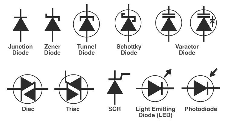
The above image illustrates the different types of available diodes with their symbols.
This PCB diode generates light when an electric current flows between the electrodes. In other words, this produces light when enough forwarding current is flowing through these diodes.
Due to the coherent light it produces, it is a unique kind of diode. Developers use this kind of diode when designing CD drives, DVD players, and laser devices. These are more expensive than LEDs but less expensive than other laser producers. The only disadvantage of these diodes is their short lifespan.
The avalanche phenomenon is functioning behind this to operate this reverse bias type of diode. The breakdown of the avalanche occurs when the voltage drop is steady and independent of the current. This type of diode is essential for picture detection purposes because of there high sensitivity to light.
Due to its ability to deliver a consistent reference voltage, it is the most practical sort of diode. This malfunctions when a particular voltage is applied and is performed in reverse bias. A steady voltage is produced if the resistor's current flow is restricted. Zener diodes are frequently utilized in power supply to give a reference voltage.
It has a lower forward voltage than all other silicon PN junction diodes. Low current areas will show a drop, and voltage levels are between 0.15 and 0.4 volts at that time. To achieve that performance, these are built differently. in order to achieve functioning these diodes are built with specific differences. The usage of Schottky diodes in rectifier applications is widespread.
A photodiode can detect even very modest current flows brought on by light. These are highly beneficial in light detection. These reverse-biased diodes are essential components when designing Photometers and solar cells. They even serve as a source of electricity.
PCB diodes for rectifiers are another name for P-N junction diodes. Semiconductor material makes up these diodes employed in the rectification process. Two semiconductor layers are included in the P-N junction diode. P-type doping is present in one semiconductor material layer, while N-type doping is present in the other layer. P-N junctions are created when layers of both P and N types are combined.
Generally, all electrical circuits use diodes. Semiconductor diodes are applied to the circuit to strengthen and increase its lifespan. Integrated circuits have improved due to the continuous development of semiconductor diodes, which has also contributed to other fields.
The unidirectional conductivity of a diode is utilized to turn on or off a circuit in digital and integrated circuits, and this technology has been widely adopted. Switching diodes, for instance, can maintain the functionality of conventional switches while providing good circuit protection, preventing short-circuit burnout, etc. The switch's quick switching speed is another advantage of the switch diode.
Limiter circuits are frequently employed in electrical circuits to process various signals. Within a predetermined level range, it is used to intentionally transmit a portion of the signal. Even while most diodes can be employed as limiters, there are instances when specialized limit diodes, like protective instruments, are required.
Typically, voltage stabilizing circuits use Zener diodes. It was made with the utilization of a unique manufacturing process. This is a process called a cross-junction silicon semiconductor diode. This unique diode is simple to form an electric field, has a high impurity concentration, and has a high charge density in the charge space. When the voltage across the Zener diode increases to a specific value, there will be a sudden increase in the reverse current. So that leads to the reverse breakdown of the diode.
Varactor diodes are frequently employed in varactor circuits to achieve intelligent control, optimization, frequency modulation, and scanning oscillation of circuits. They are commonly used in microwave circuits, including frequency multipliers, parametric amplifiers, and electronic tuners.
The application of the diode types in the different applications varies according to the project's requirements. When considering the same product developed by other industrial companies, the diodes' types and quality change according to the customer requirements and technologies.
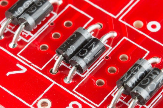
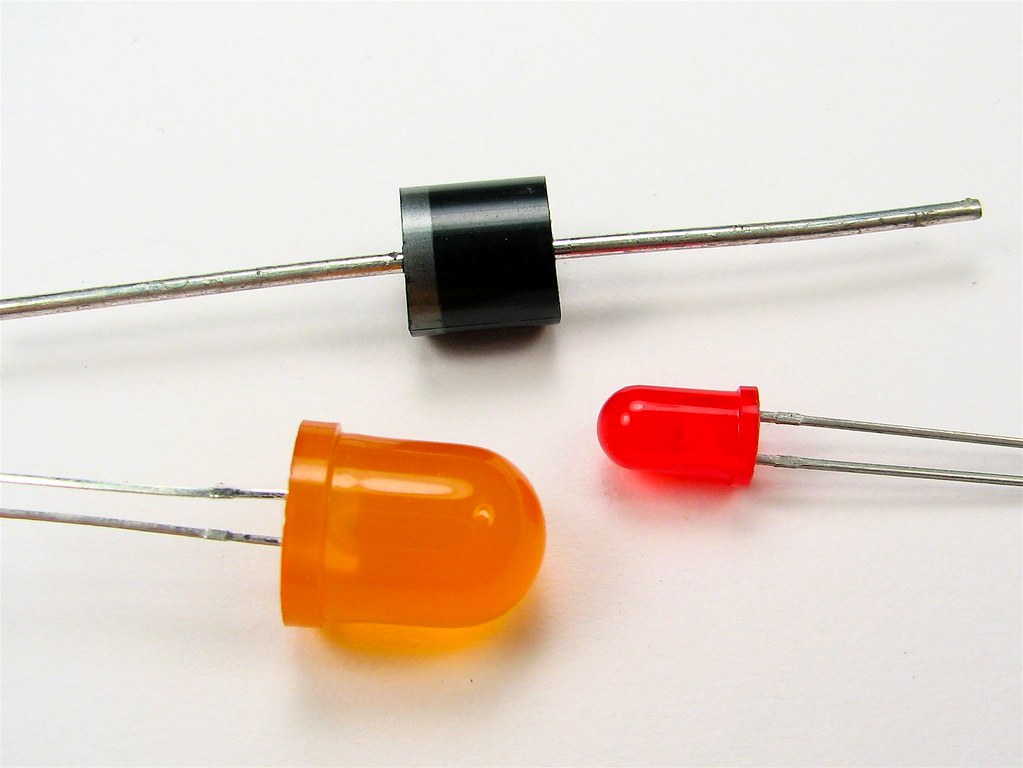
There are two methods that can follow when connecting the diodes to the PCBs. Those use Through Hole Technology (THT) and Surface Mount Technology (SMT). The above figure illustrates a diode connected to the PCB using THT technology.
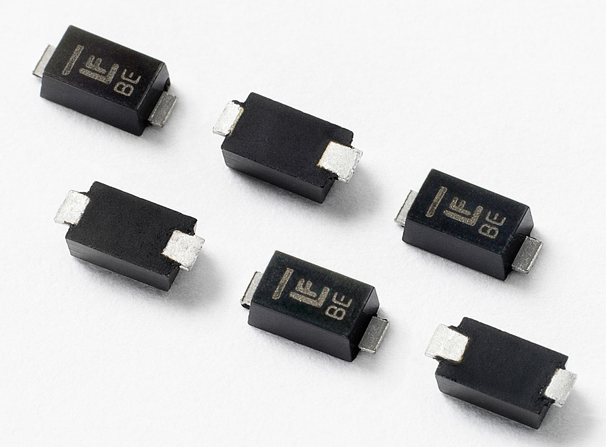
The above image is an example diode for an SMT-type diode. When connecting a diode to a PCB using the above-mentioned soldering temperature, the required amount of solder to be in the diode leads to the standards that have to follow in soldering given according to the purpose that the PCB is going to use.
The PCB designer will identify the biasing (forward and reverse) according to the requirement and the functionality of the PCB. Furthermore, you have to consider the following factors when connecting the diode to the PCB.
You have to consider all the above factors when selecting the diode for the PCB. Because there are many diodes that function as the same damaged diode. Still, few of them will be suitable for the operation of the PCB.
For the replacement of a damaged diode in a designed PCB, you can use the following procedure,
Visual inspection is a step that you can use for verifying the soldering of the diode. Moreover, the microscopic view can check the correct soldering leads. The soldering will mostly follow the industry's IPC-A-610 standards.
Diode testing before assembling is a critical step that has to carry out in developing the PCBs. There are two standard methods for the testing of diodes. Those are,
The diode test mode is the best way to test the PCB diodes. By following the below procedure you can check the diodes,
By following the procedure above, you can identify the diode condition. From there, you can decide whether to replace it or not.
The diodes are the main component of developing the PCBs. The functionality of the diodes varies as reverse-biased and forward-biased. Considering factors like the impedance and the current flow, you can apply the diodes to the necessary parts of the PCB design. Since there are several types of diodes, they carry out different functionalities. You can identify the essential diode type with the consideration of the functionality, the type of PCBs that will develop, and the environment in which the PCB is used. Since there are many applications of diodes, like the other main electronic components, diodes are one of the main components in designing PCBs. With the development of electronic technology, diodes play a significant role in controlling the elements.
Still, need help? Contact Us: support@nextpcb.com
Need a PCB or PCBA quote? Quote now


 Surface

