
 Surface


Stacy Lu

 NextPCB Capabilities
Printed Circuit Boards
NextPCB Capabilities
Printed Circuit Boards
 PCB Assembly
 Layer Buildup
 SMD-Stencils
 PCB Design-Aid & Layout
 Mechanics
 Quality
 Drills & Throughplating
 Factory & Certificate
 PCB Assembly Factory Show
Certificate
PCB Assembly Factory Show
Certificate
Support Team
Feedback:
support@nextpcb.com


Table of Contents
Electrolytic Capacitors (E-Caps) are crucial in circuit design, particularly in applications requiring large energy storage and low-frequency signal bypassing. To understand the engineering applications of E-Caps, one must first grasp the core physical principle enabling their high capacitance density: Electrochemical Anodization.
The core mechanism of E-Caps involves the anode metal (typically Aluminum, Tantalum, or Niobium) forming an extremely thin insulating oxide layer through the process of Electrochemical Anodization in a specific electrochemical environment. During this process, the liquid electrolyte provides the oxygen necessary for oxide formation.
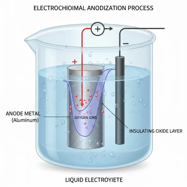
Image generated by AI (nanobanana).
The anode foil, when energized in an electrolytic solution, undergoes oxidation, forming a dense, high-dielectric-strength layer of aluminum oxide (Al2O3) on its surface. Since capacitance C is inversely proportional to the dielectric layer thickness d, and this layer is controlled down to the nanometer scale via anodization, E-Caps can store significant charge in a small volume, achieving extremely high capacitance density. This oxide film functions directly as the capacitor's dielectric.
A typical aluminum electrolytic capacitor consists of four main components: the etched anode aluminum foil (to maximize surface area), the separator paper saturated with liquid electrolyte, the cathode aluminum foil, and the casing.
The separator paper prevents short circuits between the anode and cathode foils and serves as a reservoir for the liquid electrolyte, which is vital for extending the capacitor's lifespan.
From an engineering perspective, a key distinction is the current path: the cathode aluminum foil primarily acts as a current collector for establishing electrical contact with the electrolyte. The element truly functioning as the second electrode—the "true cathode"—is the conductive liquid or solid electrolyte itself. The electrolyte is in direct contact with the dielectric oxide layer, facilitating charge collection and transfer.
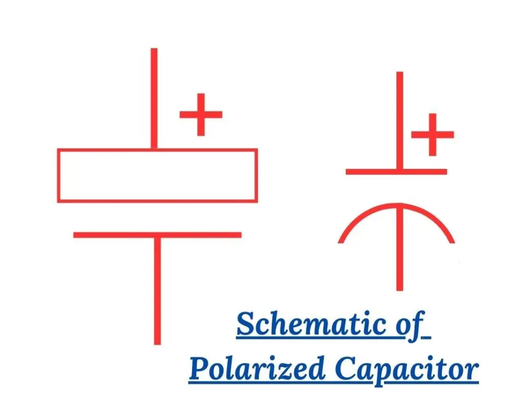
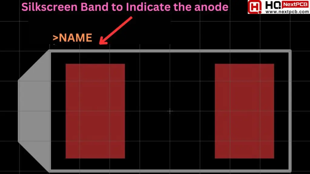
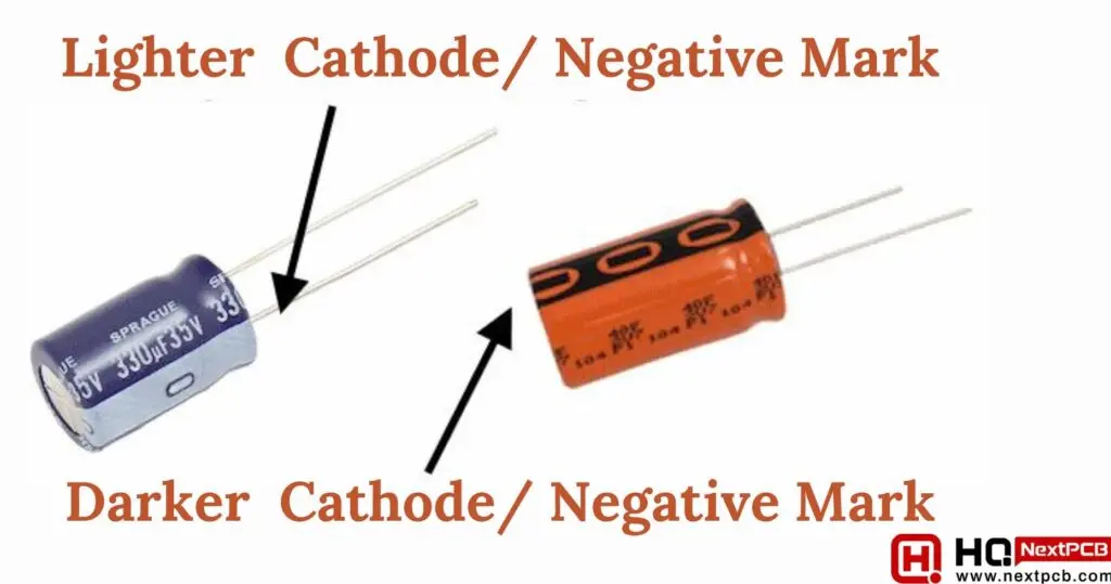
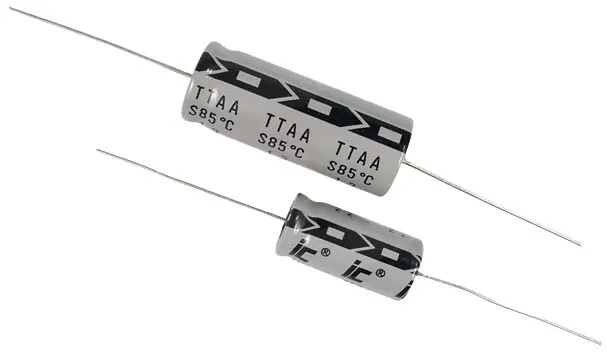
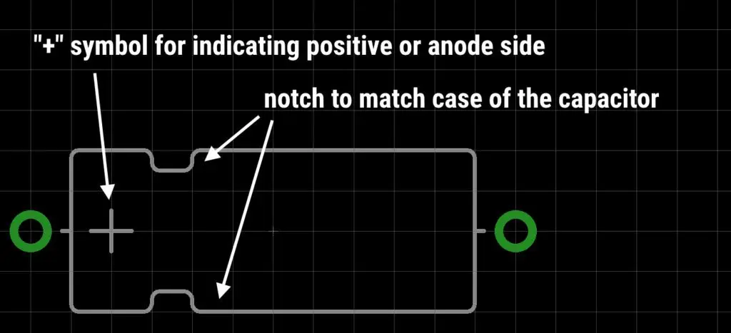
The construction of electrolytic capacitors dictates their inherent polarity, meaning they must always be operated with a higher potential on the anode (positive terminal) than on the cathode (negative terminal). This polarity requirement is a direct physical constraint imposed by the manufacturing process.
> Read How to Determine the Polarity of a Capacitor?
If the operating polarity is reversed, the asymmetrical structure leads to the destruction of the dielectric oxide layer. This breakdown causes a dramatic increase in leakage current, generating enormous internal I2R heat. The high temperature rapidly accelerates the vaporization of the liquid electrolyte, causing rapid internal pressure buildup that can result in an explosion or fire, damaging surrounding components and personnel.
Therefore, strict adherence to polarity is a direct structural constraint. In power supply design, reverse polarity connection is a common and catastrophic error, often occurring at the rectifier stage or DC-DC converter input. Correct polarity connection is fundamental to ensuring circuit safety and reliability.
The performance and reliability of electrolytic capacitors are primarily determined by their anode material and the type of electrolyte used. Based on these two factors, E-Caps are broadly classified into two families: Wet/Non-Solid and Solid.
Based on the physical state of the electrolyte, they are subdivided:
In traditional wet aluminum E-Caps, the liquid electrolyte is not just a conductor for the cathode; its more crucial function is providing the oxygen necessary for the continuous "self-healing" process of the dielectric oxide layer when the capacitor is under voltage stress.
This mechanism relies on the chemical compounds present in the liquid electrolyte. When minor defects occur in the dielectric oxide layer, the electrolyte reacts with the exposed anode metal in a secondary anodization reaction, regenerating the protective oxide layer. This self-repair ability is vital for the long-term stability of wet E-Caps, though it is the liquid electrolyte's finite presence (vaporization) that ultimately limits their lifespan.
To overcome the inherent limitations of wet electrolytes, solid polymer electrolytes have been increasingly adopted in engineering. Solid polymer capacitors due to their significant conductive advantages, fundamentally alter the performance envelope, significantly improving system stability and longevity.
Solid polymer capacitors exhibit much lower Equivalent Series Resistance (ESR). Low ESR means less internal heat generation (P = I2 × ESR) under the same current stress. Consequently, solid polymer capacitors can handle significantly higher ripple current ratings—up to 6 times greater than standard wet aluminum counterparts.
| Characteristic | Wet Aluminum Electrolytic Caps | Solid Polymer Electrolytic Caps | Engineering Implication |
|---|---|---|---|
| Electrolyte Type | Liquid/Non-Solid (Liquid Electrolyte, e.g., Ethylene Glycol/Borates) | Solid (Conductive Polymer) | Wet type life is limited by liquid evaporation, and possesses self-healing capability. |
| Equivalent Series Resistance (ESR) | Medium to High; Highly temperature sensitive | Very Low; Highly stable | Significantly improves ripple current handling and reduces internal heat generation (P = I2 × ESR). |
| Ripple Current Rating | Lower | Up to 6 times higher | Reduces the number of parallel capacitors required in power applications. |
| Effective Operating Freq. Range | Max effective frequency is ~100 kHz | Up to 500 kHz or higher | Solid types are better suited for higher-frequency switching regulator designs. |
| Life Multiplier | Life is halved for every 10°C rise in temp | Expected life increases 10X for every 20°C decrease in temp | Critical for high-reliability, long-term equipment operation. |
The actual capacitor is modeled as an Equivalent Series Circuit (ESC), including the ideal capacitance (C), Equivalent Series Resistance (ESR), and Equivalent Series Inductance (ESL).
> Key Parasitic Parameters: ESR, ESL, and Self-Resonant Frequency (SRF)
ESR is the inherent resistance of the capacitor's leads, foils, and the electrolyte itself.
High ESR causes energy dissipation as heat (I2R), raising the capacitor's internal temperature. High ESR leads to higher energy loss, which directly reduces the power conversion efficiency of the power supply. In filtering circuits, high ESR degrades efficiency and increases output voltage ripple.
To reduce total ESR, designs must select inherently low ESR components, such as solid polymer capacitors. Additionally, in Power Delivery Network (PDN) design, connecting multiple capacitors in parallel effectively divides the total ESR by the number of parallel components (n), significantly reducing heat dissipation and increasing ripple current handling.
ESL is the parasitic inductance introduced by the capacitor's leads and internal coiled structure.
High ESL causes the capacitor's impedance to rise sharply at high frequencies, severely limiting its effectiveness as a decoupling or filtering component, and potentially leading to signal integrity issues and EMI noise. Standard electrolytic capacitors typically have ESL values of 5 to 10 nH, much higher than Multilayer Ceramic Capacitors (MLCCs).
The key to minimizing ESL is minimizing the current loop area. PCB designers should adhere to the following principles:
> Recommend reading: Electrolytic Capacitor Design PCB Layout Principles
The capacitor's total impedance Z is the total opposition to AC current flow, influenced by C, ESR, and ESL. Understanding how impedance changes with frequency is fundamental to selecting appropriate capacitors for filtering and decoupling.
When charting the capacitor's impedance (Z) against frequency (f), the resulting curve exhibits three critical regions:
| Frequency Region | Dominant Element | Impedance Behavior (Z) | Implication for PCB Design |
|---|---|---|---|
| Low Frequency (Below SRF) | Capacitance (XC) | Decreases (∝ 1/f) | Effective for large bulk energy storage and low-frequency ripple filtering (e.g., 120 Hz mains ripple). |
| Self-Resonant Frequency (SRF) | Equivalent Series Resistance (ESR) | Reaches Minimum (Z ≈ ESR) | Peak filtering efficiency; determines ripple current handling capability. |
| High Frequency (Above SRF) | Equivalent Series Inductance (ESL) | Increases (∝ f) | Component behaves like an inductor, ineffective for high-frequency decoupling/noise suppression. |
Designers must recognize the dual role of ESR: while high ESR causes heating and ripple, it also effectively dampens the impedance curve, flattening the response around the SRF. In complex PDN designs using multiple capacitors in parallel, aiming for extremely low ESR can be counterproductive, potentially leading to dangerous high impedance peaks between the resonant frequencies of the parallel capacitors. These peaks, if exceeding the target impedance line (ZT), can severely compromise PDN stability.
Due to ESL limitations, electrolytic capacitors' effective frequency response is typically limited to the 100 kHz to 500 kHz range. Consequently, E-Caps must be used in conjunction with low ESL capacitors (such as MLCCs) to ensure full frequency spectrum coverage, from low-frequency bulk storage to high-frequency noise suppression.
For any high-reliability system, the finite lifespan of electrolytic capacitors is a critical parameter that must be factored into the engineering design. In industrial applications like motor drives, the aluminum electrolytic capacitor is generally considered the weak link limiting the system's life expectancy.
Wet aluminum electrolytic capacitors are subject to a finite wear-out life, with the primary physical failure mode being the vaporization and diffusion of the liquid electrolyte.
>Further reading Electronic Components: Key Parameters and Design Optimization for PCBs
The capacitor's internal core temperature is the sum of the ambient temperature and the self-heating generated by ripple current flowing through the ESR. At elevated temperatures, the vapor pressure of the liquid electrolyte sharply increases, accelerating the diffusion rate through the polymer seals. This thermal stress rapidly depletes the liquid electrolyte, causing capacitance to drop and ESR to rise, ultimately leading to component failure. This is a severe challenge for equipment operating in high ambient temperatures, such as industrial controls or automotive electronics.
The wear-out rate of a capacitor is exponentially related to its core temperature. According to manufacturer specifications and empirical data, the projected life of aluminum electrolytic capacitors follows the famous "10°C Rule": The estimated life of a capacitor is halved for every 10°C increase in its operating temperature.
This means component selection should not be based solely on capacitance and voltage. Given that temperature determines longevity, the design objective must shift toward selecting an appropriate rated life based on the application's expected maximum core temperature. For example, a capacitor rated for 7,000 hours @ 105°C will have its actual life double to 14,000 hours if operated continuously at 95°C.
To ensure system reliability and performance, engineers must actively manage the core temperature of electrolytic capacitors.
The capacitor's internal core temperature is the sum of the ambient temperature and the temperature rise due to self-heating. This self-heating is estimated by the formula Pdissipated = I2ripple × ESR.
Effective thermal management must be integrated into the PCB layout. Mitigation techniques and layout optimization include:
Understanding the physical principles, parasitic effects, and reliability limits of electrolytic capacitors provides the necessary engineering context for PCB beginners to tackle advanced implementation challenges.
To translate this foundational knowledge into reliable PCB design practice, engineers must delve into component selection, layout optimization, and manufacturing file preparation. After mastering the physics of E-Caps, leverage the in-depth resources from NextPCB to bridge the gap from concept to implemented design:
The reliable performance and expected lifespan of electrolytic capacitors are fundamentally governed by their intrinsic physics and extrinsic design management. For engineers, mastering E-Cap application means precisely controlling thermal stress, comprehensively accounting for parasitic effects, and strictly adhering to polarity requirements.
NextPCB supports engineers by integrating component integrity into the manufacturing and assembly process. Utilizing NextPCB's One-Stop BOM Service enables a streamlined manufacturing ecosystem that merges component procurement, engineering verification, lifecycle insight, fabrication, and assembly into a single, synchronized workflow. This integration minimizes the risks associated with hand-offs, blind spots, and delays common in traditional supply chains.
Furthermore, by leveraging NextPCB's affiliated platform, HQOnline, engineers ensure access to high-quality, verified components. HQOnline provides real-time component pricing, global availability checks, and access to over 600,000 locally verified components. This means the reliable electrolytic capacitor you specify in your design can be sourced quickly and accurately for your PCB build. Choose NextPCB for smarter sourcing, safer components, faster builds, and stronger products to power your hardware projects.
In conclusion, the engineering and practical application of electrolytic capacitors require a deep understanding of their physical principles, their limitations, and their behavior within specific circuit designs. By selecting the right type of capacitor, managing temperature stress, and minimizing parasitic effects like ESR and ESL, engineers can enhance both the performance and lifespan of their designs. Additionally, leveraging resources like NextPCB and HQOnline ensures that components are sourced reliably and efficiently, streamlining the design process and reducing the potential for errors or delays.
With proper knowledge and the right tools, electrolytic capacitors can be integrated into a wide range of applications with confidence, from power supplies to automotive electronics, ensuring long-term reliability and optimal performance.

Still, need help? Contact Us: support@nextpcb.com
Need a PCB or PCBA quote? Quote now

