



Julia Wu - Senior Sales Engineer at NextPCB.com

 NextPCB Capabilities
Printed Circuit Boards
NextPCB Capabilities
Printed Circuit Boards
 PCB Assembly
 Layer Buildup
 SMD-Stencils
 PCB Design-Aid & Layout
 Mechanics
 Quality
 Drills & Throughplating
 Factory & Certificate
 PCB Assembly Factory Show
Certificate
PCB Assembly Factory Show
Certificate

Support Team
Feedback:
support@nextpcb.com


PTFE (Polytetrafluoroethylene), commonly known as Teflon, is a high-performance material widely used in the chemical and electronics industries. Its unique physical and chemical properties make PTFE an ideal material for many advanced technology applications, particularly in the electrical and electronic sectors. This article will discuss the dielectric constant of PTFE and its applications and advantages in printed circuit boards (PCBs).
The dielectric constant (also referred to as relative permittivity, εr) is a parameter that describes how a material responds to an electric field, specifically its ability to polarize in the presence of an electric field. A higher dielectric constant indicates a stronger response to the electric field. PTFE has a relatively low dielectric constant, typically ranging from 2.0 to 2.3, which is lower than most common materials. For comparison, the dielectric constant of air is 1.0, and water's dielectric constant is around 80. The low dielectric constant of PTFE makes it an ideal choice for high-frequency electrical and electronic applications.
PTFE was discovered in 1938 by chemist Roy Plunkett at DuPont's Jackson Laboratory, patented in 1941, and put into commercial production by DuPont in 1950. It remains one of the most extensively characterized industrial polymers, which is part of why its electrical properties are so well documented and consistent across independent test sources.
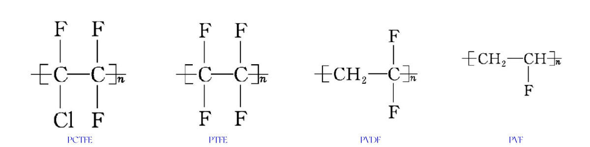
This low dielectric constant traces back to PTFE's molecular structure. Unlike related fluoropolymers such as PCTFE, PVDF, or PVF — which substitute some fluorine atoms with chlorine or hydrogen — PTFE's carbon backbone is fully and symmetrically surrounded by fluorine atoms. This complete fluorination minimizes molecular polarity, which is the direct cause of PTFE's exceptionally low, stable dielectric constant.
The dielectric constant of PTFE (also known as Teflon) is relatively low, typically between 2.0 and 2.3. This low Teflon dielectric constant makes it ideal for high-frequency applications, such as RF (radio frequency) and microwave circuits, where reducing signal delay and attenuation is critical. PTFE helps optimize signal transmission speed and circuit performance.
PTFE's dielectric constant is influenced by temperature and frequency. As temperature increases, the dielectric constant of PTFE may rise slightly. Additionally, at high frequencies, PTFE's molecular polarization may not be able to keep pace with rapid changes in the electric field, leading to changes in the dielectric constant. Engineers sometimes call this same property "permittivity" — dielectric constant and relative permittivity refer to the same value (εr), just different terminology used in RF versus materials-science contexts.
Dielectric constant is only one part of PTFE's electrical profile. Design engineers evaluating PTFE for insulation, high-voltage, or RF substrate use also need to know how well it blocks current flow (resistivity/conductivity) and how much voltage it can withstand before breaking down (dielectric strength). The table below summarizes typical published values; exact figures vary by resin grade, film thickness, and test method (ASTM D149, D257, D150).
| Electrical Property | Typical Value | Why It Matters |
|---|---|---|
| Dielectric constant (εr / permittivity) | 2.0 – 2.1 | Lower value = faster, cleaner signal propagation |
| Dissipation factor (loss tangent) | 0.0002 – 0.0004 | Very low signal/energy loss as heat at high frequency |
| Dielectric strength (breakdown voltage) | ~60 – 170 kV/mm (thin films can exceed this; thicker sections are lower) | Higher value = withstands more voltage before arcing/breakdown |
| Volume resistivity | >10¹⁸ Ω·cm | Near-zero current leakage through the bulk material |
| Surface resistivity | >10¹⁶ Ω/sq (dry conditions) | Minimal surface tracking/leakage current |
No — PTFE is not electrically conductive. It is one of the most effective electrical insulators available, with a volume resistivity greater than 10¹⁸ Ω·cm. This means it allows almost no current to pass through its bulk, which is why it is used as insulation for high-voltage wiring, connectors, and cable jacketing rather than as any kind of conductor.
>> Because dielectric constant directly affects trace impedance, if you're designing a PTFE-based high-frequency board, use our PCB impedance calculator to model how PTFE's of 2.0–2.1 affects your target impedance before finalizing stack-up.
PTFE's volume resistivity — its resistance to current flow through the material — typically exceeds 10¹⁸ Ω·cm, among the highest of any commercial polymer. Its surface resistivity, which governs leakage current along the material's surface rather than through it, is similarly high (generally above 10¹⁶ Ω/sq under dry conditions), though surface resistivity can drop somewhat in humid environments on any insulator, PTFE included. Because PTFE does not absorb moisture, its resistivity stays more stable across humidity levels than many alternative insulating materials. In practice, this stability holds up under real-world exposure: PTFE's volume resistivity shows no significant drop even after long-term immersion in water, and its surface resistivity remains essentially unchanged even in 100% relative humidity air — a level of moisture stability most other insulating polymers cannot match.
Dielectric strength (breakdown voltage) measures the maximum electric field a material can withstand before it fails and allows current to arc through it. PTFE's dielectric strength is commonly cited in the range of roughly 60–170 kV/mm, with very thin, highly purified films tested under ASTM D149 sometimes exceeding this range and thicker sections measuring lower — dielectric strength is thickness-dependent for all insulating materials, not just PTFE. Combined with its low dielectric constant and low dissipation factor, this high breakdown voltage is why PTFE performs well in high-voltage wire insulation, connectors, and RF components where signal integrity and voltage withstand both matter.
PTFE also has outstanding arc resistance — the ability to withstand a high-voltage surface discharge without forming a permanent conductive track. When an electrical arc occurs on most plastics, the surface carbonizes and leaves behind a conductive residue that can eventually cause a short circuit. PTFE behaves differently: under arcing, it decomposes into small, volatile fluorocarbon molecules that evaporate rather than carbonize, so no conductive path is left behind. Independent arc-resistance testing has measured PTFE's arc resistance at over 300 seconds — the highest among common engineering plastics (compared with roughly 100–190 seconds for materials like polyimide, LCP, and PET). This is a key reason PTFE is used in high-voltage switchgear, connectors, and insulating components.
PTFE is widely used in electrical wire insulation, circuit board substrates, capacitors, and other electronic components due to its excellent electrical properties. Specifically, PTFE excels in the following areas:
PTFE features extremely low dielectric loss and a stable dielectric constant. It maintains excellent electrical performance under varying temperature and frequency conditions, which is crucial for high-frequency signal transmission. This is particularly beneficial in RF and microwave circuits, where PTFE helps reduce signal loss and ensures signal integrity.
PTFE offers excellent resistance to high voltage and is highly resistant to chemical corrosion. It can withstand exposure to most acids, bases, and other aggressive chemicals, making it suitable for harsh environments where other materials would degrade.
PTFE can withstand temperatures as high as 260°C without compromising its insulating properties, making it suitable for high-temperature electronic components and circuit board designs. This makes it ideal for use in aerospace, telecommunications, and other industries requiring materials that perform reliably in extreme conditions.
PTFE has a Limiting Oxygen Index (LOI) of about 95% — meaning it requires an atmosphere of roughly 95% oxygen to sustain combustion, making it one of the most flame-resistant plastics available. PTFE meets the UL94 V-0 flammability rating without any added flame retardants, which is a meaningful advantage in electronics and cable applications where flame-retardant additives can otherwise degrade electrical performance.
Due to its excellent electrical properties, PTFE is widely used in the manufacturing of printed circuit boards (PCBs), particularly in high-frequency and radio-frequency (RF) applications. Here are the main characteristics of PTFE-based PCBs:
PTFE's low dielectric constant and low dielectric loss make it an ideal material for high-frequency PCBs. In RF and microwave applications, PTFE ensures stable signal transmission, reducing signal reflection and attenuation, thereby improving overall circuit performance.
PTFE has exceptional chemical stability, making it highly resistant to acids, bases, and other corrosive chemicals. This characteristic makes PTFE PCBs particularly suitable for applications in harsh environments, such as aerospace, industrial, and chemical processing.
With its high dielectric strength and low dielectric constant, PTFE is an excellent choice for high-performance PCBs. PTFE PCBs help prevent electrical breakdown and ensure stable, clear signal transmission, improving the reliability of the circuit.
PTFE is non-hygroscopic, meaning it does not absorb moisture, which helps prevent the ingress of water and humidity into the PCB. This characteristic protects the components and circuitry from moisture-related damage and extends the service life of electronic devices. Additionally, PTFE maintains stable electrical properties at high temperatures, making it ideal for use in electronics exposed to extreme conditions.
PTFE PCBs are commonly used in RF and microwave devices, especially in applications that require high precision and performance. NextPCB supports RF and microwave PCB manufacturing for satellite communications, radar systems, and high-frequency wireless communication.
Due to its low dielectric constant, PTFE PCBs are crucial in satellite communication and radar systems. They reduce signal loss and ensure accurate signal transmission, which is critical for high-performance systems.
PTFE PCBs are essential in modern communication technology, where high-frequency signal integrity is vital. PTFE helps reduce electromagnetic interference (EMI) and ensures high-quality data transmission, making it widely used in high-speed data transfer systems.
In addition to its use in PCBs, PTFE is also employed in various other electronic components and materials due to its low friction coefficient, high corrosion resistance, and high-temperature stability:
For engineers choosing a PCB substrate, it helps to see PTFE's electrical properties next to the two other most common options: standard FR4 and Rogers hydrocarbon/ceramic laminates. This is a general materials comparison; always confirm the exact grade's datasheet with your fabricator before finalizing a design.
| Property | PTFE | Standard FR4 | Rogers RO4003C (typical) |
|---|---|---|---|
| Dielectric constant (εr) | 2.0 – 2.1 | ~4.2 – 4.5 | ~3.38 |
| Dissipation factor | 0.0002 – 0.0004 | ~0.02 | ~0.0027 |
| Moisture absorption | Negligible (non-hygroscopic) | Moderate | Low |
| Best-suited use case | RF/microwave, radar, high-voltage insulation | General-purpose digital/consumer PCBs | Mid-frequency RF where cost vs. PTFE is a factor |
Not sure which substrate fits your design — PTFE, FR4, or a Rogers laminate? Talk to our engineering team for material selection guidance based on your frequency range and budget.
Polytetrafluoroethylene (PTFE) offers numerous excellent properties, including resistance to strong acids, alkalis, oxidizing agents, various solvents, high temperatures up to 260°C, low temperatures down to -192°C, non-aging, a very low coefficient of friction, and high electrical insulation. While its overall performance is relatively stable under typical usage, its shortcomings are quite apparent. While developing and utilizing the various outstanding characteristics of PTFE, its many defects still limit its scope of application.
Pure PTFE products typically have a hardness of around Shore 55, which means that PTFE materials are not able to withstand high pressure without deforming. For instance, gaskets made from PTFE are prone to plastic deformation or cold flow when tightened excessively. This poor creep resistance necessitates modification by adding fillers to enhance its performance.
Although PTFE products have a very low friction coefficient, making them widely used for their lubricating properties, they lack sufficient wear resistance when in motion against counterpart materials. Mechanical strength is poor, and rigidity is insufficient. For example, PTFE-based bearings used in oil-free lubrication applications require frequent replacement due to wear, which affects normal usage. This issue can be addressed by incorporating wear-resistant materials.
PTFE has low surface energy, which gives it its non-stick properties. Its surface energy is approximately 0.019 J/m² (19 mN/m) — among the lowest of any known solid material. While this is beneficial for applications in textiles, adhesives, and fluids, it also limits its industrial use, particularly when bonding with other materials. To overcome this, surface treatments such as sodium treatment can be applied to enable better adhesion to other substances.
PTFE resins, mainly produced by compression molding, have poor flowability. PTFE resin powder has a high melt viscosity, which makes it difficult to process using conventional thermoplastic forming methods. Even at elevated temperatures, PTFE does not flow easily, making molding and extrusion processes challenging and cost-intensive. This raises the cost of processing, especially since PTFE raw materials are relatively expensive. The complex processing methods further limit its application range.
PTFE exhibits a relatively high coefficient of thermal expansion, which changes irregularly with temperature. This causes significant expansion and contraction with temperature variations, leading to poor dimensional stability during processing. For instance, when used in anti-corrosion equipment such as container linings, the mismatch in thermal expansion between the PTFE lining and metal shell can lead to deformation, delamination, and collapse due to thermal cycling and negative pressure during operation. Therefore, PTFE is not suitable for precise machining of components.
While PTFE is generally safe and non-toxic, when heated to temperatures above 380°C, it can release toxic gases and ions. This presents a safety hazard, particularly when exposed to open flames, welding, or high-temperature heating. Proper ventilation and safety measures must be ensured to prevent harmful emissions.
Despite PTFE's excellent electrical properties, including its low dielectric constant and high resistance, it is highly prone to static electricity due to the nature of sintered PTFE products. In many applications, static discharge is undesirable. To address this issue, anti-static additives can be incorporated to make PTFE products anti-static.
PTFE products are typically molded under high pressure, resulting in a dense material with minimal shrinkage. However, if the molding pressure is too low, the material can undergo significant and irregular shrinkage during cooling. PTFE components also require a large tolerance range and cannot be precision-machined like metals. The linear thermal expansion of PTFE is about ten times that of iron, which can lead to tolerance issues in applications where precise dimensions are required.
Due to PTFE's inert nature, it does not easily bond with other materials. Adhesion or welding issues are common. The most common bonding methods include discharge treatment and alkali metal solution treatment, which can activate the PTFE surface to enable bonding with other materials. Plasma or glow discharge processes can be used to activate PTFE components, while alkali metal solutions such as naphthalene-sodium complexes are also used. However, these processes still have limitations in terms of bonding strength and temperature resistance, and the bond strength may not be sufficient for demanding applications. Thermal welding can be used to join PTFE components, but the welding rod material is often slightly different from PTFE, resulting in weak weld joints that require further improvement.
PTFE has a low thermal conductivity, which means it is not efficient at heat dissipation. This can lead to overheating in thick-walled products, such as bearings. While adding filler materials can somewhat improve thermal conductivity, PTFE still remains a poor conductor of heat. This issue must be addressed in applications requiring high heat transfer, as the slow heat dissipation can cause temperature imbalances within the material.
Polytetrafluoroethylene (PTFE), also widely known as Teflon, boasts exceptional properties such as excellent moisture resistance, non-stick characteristics (water and oil repellent), high-temperature stability, low-temperature toughness, aging resistance, and non-flammability. These properties make it highly suitable for applications in aggressive environments, such as in pipelines, containers, pumps, valves, as well as radar and high-frequency communication equipment. Additionally, PTFE is widely used in electrical, electronic, and aerospace industries where high insulation properties are critical.
However, despite its outstanding performance, PTFE still has some limitations in terms of its overall properties. Certain drawbacks, especially under extreme working conditions, have constrained its broader usage. To fully expand the potential applications of PTFE, it is necessary to address these limitations and explore methods for improving its performance.
Overall, PTFE (or Teflon) with its low dielectric constant, high dielectric strength, corrosion resistance, and high-temperature tolerance has become an indispensable high-performance material in the electronics industry. In high-frequency circuit boards and RF applications, PTFE significantly enhances the reliability and stability of circuits due to its superior electrical properties and chemical stability. With ongoing technological advancements, it is expected that the applications of PTFE will continue to expand, providing essential support for more high-tech fields and meeting the increasingly demanding needs of industry and research.
Ready to move from material selection to production? NextPCB manufactures PTFE (Teflon) high-frequency PCBs for RF, microwave, and radar applications.
PTFE's dielectric strength is commonly cited in the range of roughly 60–170 kV/mm, depending on material thickness and test method, making it one of the highest breakdown-voltage ratings among common insulating polymers.
No. PTFE is a near-ideal electrical insulator, not a conductor, with a volume resistivity greater than 10¹⁸ Ω·cm.
PTFE's volume resistivity typically exceeds 10¹⁸ Ω·cm, and its surface resistivity is generally above 10¹⁶ Ω/sq under dry conditions — both among the highest of any commercial polymer.
Yes. "Dielectric constant" and "relative permittivity" (εr) describe the same property; PTFE's value is approximately 2.0–2.1 in both terminologies.
PTFE's dielectric constant (~2.0–2.1) and dissipation factor (~0.0002–0.0004) are both far lower than standard FR4 (~4.2–4.5 and ~0.02 respectively), which means less signal loss and delay — critical for RF, microwave, and high-speed digital designs.

Still, need help? Contact Us: support@nextpcb.com
Need a PCB or PCBA quote? Quote now

