
 NextPCB Capabilities
Printed Circuit Boards
NextPCB Capabilities
Printed Circuit Boards
 PCB Assembly
 Layer Buildup
 SMD-Stencils
 PCB Design-Aid & Layout
 Mechanics
 Quality
 Drills & Throughplating
 Factory & Certificate
 PCB Assembly Factory Show
Certificate
PCB Assembly Factory Show
Certificate
Support Team
Feedback:
support@nextpcb.com


Introduction:
In high-volume PCBA manufacturing, variation from equipment, materials, and operators means not every board will be perfect. That’s why end-of-line test systems—ICT, AOI, X-ray, Boundary-Scan, FCT, and more—are essential to ensure every assembled board shipped matches the design’s specifications and limits.
Among these, FCT (Functional Circuit Test) and ICT (In-Circuit Test) are the two most common methods. Both verify quality, but they focus on different layers of the product.
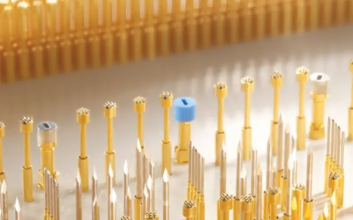
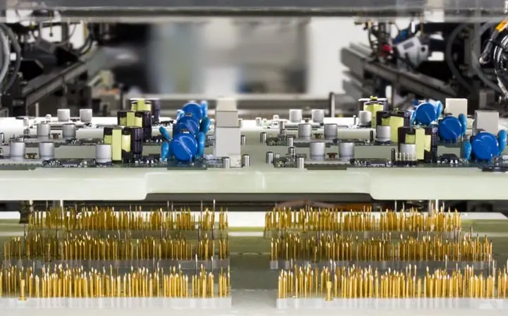
Performed immediately after SMT, ICT uses probes to contact test points and quickly detect assembly defects (opens/shorts, wrong or reversed parts) and parametric deviations (e.g., mismatched resistor values). It excels at fast, precise fault isolation—typically ~30 s to 2 min per board—but mainly verifies the static correctness of the hardware.
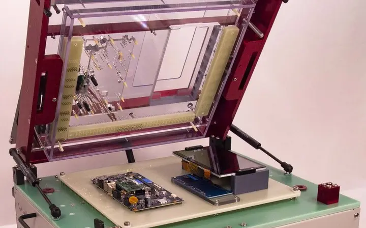
FCT runs before enclosure or at system stage, powers the board, applies realistic stimuli, and verifies system behavior. It exposes hardware–firmware interactions, timing, and logic issues under near-real operating conditions. Cycle time is longer—~1 to 10 min per board—because it validates end-to-end functionality.
Example: for a smart-home controller, an FCT station might boot firmware and inject simulated sensor signals to verify control logic and outputs.
| Defect / Test Item | ICT Recommended | FCT Recommended | Notes |
| Opens/shorts, wrong part, polarity | Yes | Bed-of-nails or Boundary-Scan alternatives | |
| R/C/diode/transistor signatures | Yes | Fast parametric windows & limits in ICT | |
| Power-rail shorts & no-load current | Yes | Yes | ICT under current-limit; FCT checks dynamic power after power-up |
| MCU/Flash connectivity, pin shorts/opens | Yes | Use JTAG/Boundary-Scan for high digital-net coverage | |
| Initial firmware/bootloader programming | Yes | Faster and more stable at ICT stage | |
| Protocol functions (UART/I²C/CAN/USB) | Yes | Loopback and interoperability in FCT | |
| Sensor chain & calibration | Yes | Requires fixture signal sources/loads | |
| RF / audio / display / buttons / UX | Yes | Best validated under near-real use | |
| Self-test & log upload behaviors | Yes | Aids repair diagnostics and traceability |
Takeaways
See Also on NextPCB:
13 Popular PCB Test Methods (context for ICT/FCT among broader methods).
PCBA manufacturing process (where ICT/FCT fit in the end-to-end flow).
PCB Assembly - The Most Comprehensive Guide
Automated Optical Inspection (AOI)
Ready to apply an ICT vs FCT strategy to your build? Explore PCB capabilities and PCBA services, then request a quote!
Still, need help? Contact Us: support@nextpcb.com
Need a PCB or PCBA quote? Quote now


 Surface

