FCT covers testing the board by stimulating its input and output signals, like the voltage, current, and power, thereby assessing its components' response. Manufacturers typically use a dedicated FCT testbed with heavy-duty contacts to help ensure the PCBs function correctly. The higher currents of this method can introduce measurement inaccuracies due to excessive contact resistance, consequently providing a comprehensive view of the PCB's functionality.
This helps to identify any potential issues that could cause problems down the line before it enters the market for release to end users. Hence, it helps reduce time-to-market and costs that come with reworking or product recall. Additionally, FCT tests can help nail potential problems with components that may have gone unnoticed during the visual inspection process.
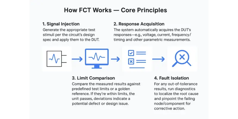
Terminology notes:
- DUT (Device Under Test) is the unit being tested.
- Pass/Fail via test limits is standard practice in production test.
- Fault isolation/diagnosis refers to locating the specific cause and site of failure.
Benefits of FCT Testing
1. Efficiency (Throughput): FCT systems run automated, scripted sequences that quickly and accurately evaluate PCBAs, reducing manual intervention and boosting line throughput—thereby improving productivity and lowering unit test cost.
2. Stability (Repeatability): Program-controlled test steps minimize operator variability. Automated instrument control and sequencing deliver consistent, repeatable results across shifts and sites.
3. Reliability (Real-world Validation): FCT powers the UUT/DUT under simulated operating conditions (loads, signals, protocols) to verify behavior in scenarios closer to end-use, improving confidence in field reliability.
4. Broad Test Coverage: Functional testers can exercise entire products—board functions, interfaces, communications, power behavior—and support domain-specific checks, giving fuller coverage than structural methods alone.
5. High Measurement Accuracy: Use of calibrated instrumentation and coordinated test software improves measurement fidelity and reduces human error; advanced supplies/meters also enhance accuracy and repeatability in automated sequences.
6. Modular, Scalable Design: Modern ATE/FCT platforms are modular (I/O, instruments, fixtures, software), allowing flexible configuration for different PCBAs, easier upgrades, and lower lifecycle cost.
7. Visualized Data & Analysis: Graphical test software provides dashboards, logging, and report generation to visualize results and speed root-cause analysis and continuous improvement.
Notes:
- FCT typically complements ICT/AOI in the line: ICT/AOI handle structural faults; FCT validates end-to-end functionality under power. Using them together increases overall quality.
Key Technical Metrics
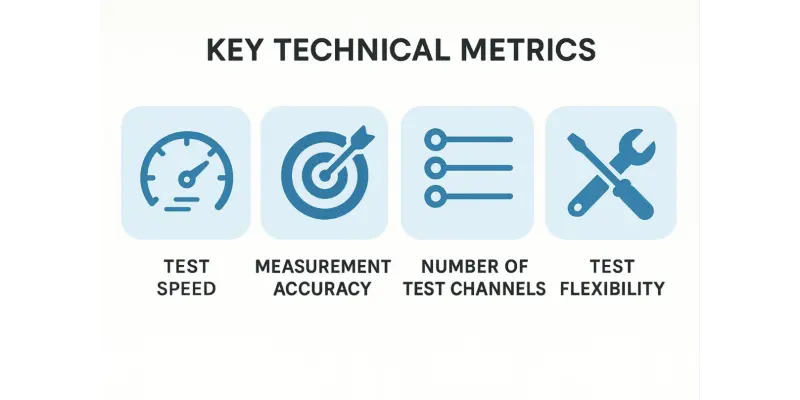
FCT (Functional Circuit Test) technical metrics mainly include:
-
Test Speed (Throughput): The time a test system takes to complete one full run on a PCBA. Higher throughput enables testing more PCBAs per shift, boosting line efficiency and reducing cost.
-
Measurement Accuracy: The degree to which the system can detect defects or out-of-tolerance behavior. Higher accuracy (tighter uncertainty/error limits) makes results more reliable and increases defect capture.
-
Number of Test Channels: Many systems provide multi-channel or parallel test capability to handle multiple boards (or multiple UUTs on a panel) simultaneously, improving overall efficiency and applicability.
-
Test Flexibility: The ability to accommodate different PCBA types and evolving requirements (e.g., reconfigurable fixtures/software, modular I/O). Greater flexibility broadens coverage and shortens changeover.
In addition, FCT setups are often categorized by control mode: manual, semi-automatic, and fully automatic. Common controller types in functional testing include MCU-based, embedded CPU-based, PC-based, and PLC-based control.
During FCT, the UUT (Unit Under Test) is exercised under simulated operating conditions (stimuli and loads) so it operates in various design states; parameters from each state are captured to verify performance. Typical measurements may include voltage, current, power, power factor, frequency, duty cycle, position sensing, LED brightness/color identification, LCD character/color checking, acoustic (sound) recognition, temperature/pressure measurement and control, precision micro-motion/actuation control, and in-system programming (ISP) of FLASH/EEPROM.
What is the Process of the Functional Circuit Test?
FCT testing is an integral part of the printed circuit board production process. The functional circuit test is the last test in the PCB production process prior to delivery to the customer. The process ensures that all electrical connections work according to the PCB schematic. The process ensures that all elements on the board are correctly assembled and operating, not just electrically connected. In practice, FCT complements AOI/ICT by applying power, loads, and signals, then checking real outputs against defined limits or a golden reference.
In practice, the basic steps of FCT include instrument hookup/fixture connection, measurement start (power-up), data acquisition, data processing, data analysis, and result reporting/disposition. During the test, representative test environments are configured—applying appropriate stimuli and loads—to exercise the DUT across operating states and verify the required functions.
Pre-FCT Visual & AOI Inspection
Before functional testing, boards undergo visual inspection and Automated Optical Inspection (AOI) to screen for assembly-related defects (misplaced/missing parts, solder bridges, opens/shorts). AOI is typically placed in-line after soldering so issues are caught early; it does not power the board and focuses on optics/imagery rather than functional behavior.
Circuit Functional Testing — System Components
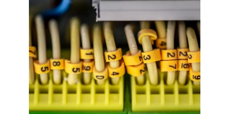
- Test Fixture / Interface: Usually a bed-of-nails fixture with pogo (spring) pins, or a harness/edge connector, to make reliable, repeatable contact with test pads and connectors.
- Instrumentation & Sensors: Power supplies, DMMs, oscilloscopes, digital I/O, comms interfaces, and any environmental/condition sensors required by the test.
- Test Software: Orchestrates stimulus/measure sequences, enforces test limits, logs results, and drives pass/fail decisions.
Circuit Functional Testing — Execution Workflow
1. Test Planning: Define test items, sequences, and limits (or a golden reference) based on the schematic/requirements.
2. Signal/Power Application: Apply power and required stimuli to the DUT (voltage, current, loads, digital/analog signals, communications).
3. Response Acquisition: Measure outputs and parametrics (voltage/current levels, timing/frequency, protocol responses) with the instruments.
4. Limit Comparison & Disposition: Compare measured results against limits to determine pass/fail.
5. Fault Isolation & Re-test: If out of tolerance, isolate the failing node/component, correct the defect, and re-verify.
6. Release: Boards that pass all tests are cleared for downstream operations and shipment.
PCB FCT Test Classification
Control mode
- Manual
- Semi-automatic
- Fully automated
The most effective PCB FCTs are often fully automatic or semi-automatic. Most functional testing methods have now become entirely automated as a result of the rapid development of technology and the need to increase production efficiency. The test software application, sometimes known as firmware by production line operators, facilitates the automation of functional testing.
To interface with the test application, operators usually employ an externally programmable instrument, such as an I/O board or digital multimeter. An FCT Test can be done using instruments attached to the device under test through a fixture and test application. On the other hand, manual and semi-automatic FCT are still popular to streamline design and lower production costs.
Controller
- MCU controller and Embedded CPU controller. These are quick and easy functional circuit testing for specialized circuits and programs for data display and output. Both have highly precise test solutions.
- PC Controller. Due to the accessibility of PC technology, it is the most commonly used FCT. Furthermore, reduced prices contribute to its appeal. In this case, the data output and file processing of the test results may be accomplished relatively easily on a workstation's operating system. Furthermore, the test application's overall functioning is relatively simple.
- PCL Controller. In development mode, it is a standard FCT that focuses on the requirement to regulate the induction component. PLCs are mostly employed in professional industrial control.
Manufacturers must ensure that their FCT testing is done according to industry standards and regulations. This includes ensuring that the test system is properly calibrated and maintained and that all elements are tested according to their specifications. Additionally, manufacturers must document all results from the tests and keep records of any changes or modifications made during the process.
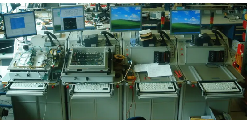
FCT Test Bed and Its Design Considerations
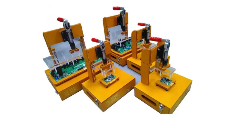
FCT test beds are designed to ensure that the PCBs are tested thoroughly and accurately. The test bed should be able to handle the product's multi-panel design, as well as accommodate pogo pins for probing. In addition, the bed should be designed so that it is able to provide a reliable connection between the probes and the PCB.
The design of the test bed should also address any potential risks of shorts or other problems that could arise due to the testing process. It should also take into consideration any elements that could be affected by Electromagnetic Interference (EMI) and take steps to mitigate this risk. Quick and easy access for maintenance and repair are also of equal importance, as it allows for efficient troubleshooting in case of problems.
All these considerations must be taken into account when designing an FCT test bed to ensure precise and straight-up results.
Common Challenges with FCT Tests
FCT tests can be challenging to perform due to their complexity and a large number of components and connections involved. Common challenges may include the need for precise control of temperature, accurate testing of components, and the difficulty in replicating complex connections.
The process can be time-consuming and expensive. Hence, it is important for manufacturers to understand how to maximize their resources when taking this type of testing. To save time and effort, some vendors perform functional testing on 50% to 100% of the product being supplied. The FCT test bed must be designed to ensure that all elements are tested accurately and reliably. In order to downplay errors, it is vital to select an FCT system that is reliable and easy to use. Ensuring that all components are tested properly during production is also important, as any errors in the test can lead to costly repairs or replacements down the line.
Investing in automated FCT systems may be considered to help streamline the process and reduce labor costs that come with manual testing operations. Some companies choose to outsource their FCT testing needs to a third-party provider who specializes in this type of testing. This helps reduce costs while still offering quality assurance for the device under test. There are a few factors to consider, though, when looking for an FCT test system.
- Firstly, it is important to evaluate the performance of the system and ensure that it meets the design's requirements.
- Secondly, weigh the cost-effectiveness of the system, as well as its accuracy and reliability. The compatibility of the system with the existing equipment and operations is also equally important.
- Ultimately, it's vital to consider the safety functions coming with the system and ensure that it meets applicable regulations/standards.
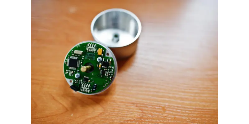
Simple Case Analysis
Assume we are producing a smartwatch that includes a heart-rate sensing circuit.
During FCT, we inject simulated heartbeat signals of varying intensity into the sensor DUT and observe its output. If the measured responses match the expected changes (i.e., within defined test limits), this portion of the circuit is considered reliable; otherwise, it requires debug/repair (rework).
Industry Applications and Future Outlook
With advances in technology—especially automation and smart manufacturing—modern FCT now supports highly automated test sequences, significantly improving throughput and measurement accuracy. In addition, integrating big-data analytics with test records enables prediction of potential failure modes and early, preventive actions (e.g., predictive maintenance and process adjustments), which is highly beneficial for improving product quality, yield, and overall reliability.
Put FCT into Practice with NextPCB
Ready to turn this FCT workflow into real yield and reliability gains? Here's a concise way to get started—using NextPCB's one-stop manufacturing and turnkey PCBA services:
- Get an instant quote & free DFM/DFA check. Upload your Gerber/BOM/Centroid to NextPCB's online quoting tools for fast pricing and free manufacturability reviews.
- Specify test coverage (AOI/ICT/FCT/X-ray). In your PCBA request, include the functional tests you need; NextPCB supports AOI, ICT, FCT, and X-ray as part of the standard quality flow.
- Share your FCT artifacts. Provide your test plan, limits/golden unit info, and fixture needs (bed-of-nails/harness). Fixture-based strategies are supported for high efficiency.
- Move fast from proto to production. Leverage quick turns, broad stackup capability, and in-line electrical testing to keep schedules tight without sacrificing quality.
- Scale with confidence (certifications & capacity). For regulated or high-reliability markets, NextPCB operates under IATF 16949, ISO 13485, ISO 9001, and ISO 14001 with modern SMT capacity.
- Cost-effective options for low volume. NextPCB highlights cost controls (panelization, universal fixtures) and notes free functional testing offers for certain low-volume PCBA scenarios. Ask the team for current eligibility.
Start now: request a PCB or PCBA instant quote and note your FCT requirements in the order; an engineer can review your test plan and fixture approach before build.
Prefer a quick walkthrough or have FCT questions (e.g., signal levels, limits, fixture choice)?
Contact NextPCB and reference your project ID for faster help.


 NextPCB Capabilities
 PCB Assembly
 Layer Buildup
 SMD-Stencils
 PCB Design-Aid & Layout
 Mechanics
 Surface
 Quality
 Drills & Throughplating
 Factory & Certificate


