NextPCB Capabilities
Printed Circuit Boards
NextPCB Capabilities
Printed Circuit Boards
 PCB Assembly
 Layer Buildup
 SMD-Stencils
 PCB Design-Aid & Layout
 Mechanics
 Quality
 Drills & Throughplating
 Factory & Certificate
 PCB Assembly Factory Show
Certificate
PCB Assembly Factory Show
Certificate
Support Team
Feedback:
support@nextpcb.com


Introduction
The ESP32 has 48 GPIO pins in total, but if you pick the wrong one for your project, you can end up with a board that won't boot, an ADC that reads garbage, or a Wi-Fi connection that drops every time you sample an analog sensor. Understanding the ESP32 pinout is not just about knowing what each pin does — it is about knowing which pins are safe to use, which ones carry hidden constraints, and which ones will cause problems you cannot easily trace back to a wiring decision. This guide covers the full ESP32 pinout in practical terms: GPIO categories, communication interfaces, safe and restricted pins, and code examples across C/C++ and MicroPython.
Before diving into the pinout details, let's briefly highlight some key features of the ESP32:
The ESP32 supports a variety of programming languages. The primary programming language for ESP32 development is C/C++, and it is typically programmed using the Arduino IDE or the ESP-IDF (Espressif IoT Development Framework), which is Espressif's official development framework for the ESP32.
Apart from C/C++, you can also use MicroPython and JavaScript (via Espruino) to program the ESP32. Here's a brief overview:
C/C++ with Arduino IDE or ESP-IDF - The Arduino IDE provides a user-friendly environment for programming the ESP32 using C/C++. Alternatively, you can use the ESP-IDF, which offers more advanced features and low-level control.
MicroPython - is a lightweight implementation of Python 3 for microcontrollers. It allows you to write Python code directly on the ESP32, providing a higher-level language for development.
Espruino - is a JavaScript interpreter for microcontrollers, and it supports the ESP32. You can use the Espruino IDE or a text editor to write JavaScript code for your ESP32.
These programming languages offer flexibility, allowing developers to choose the one that best suits their preferences and project requirements. Remember that C/C++ is the most commonly used language for ESP32 development due to its efficiency and close integration with the hardware.
Free Components Worldwide Shipping
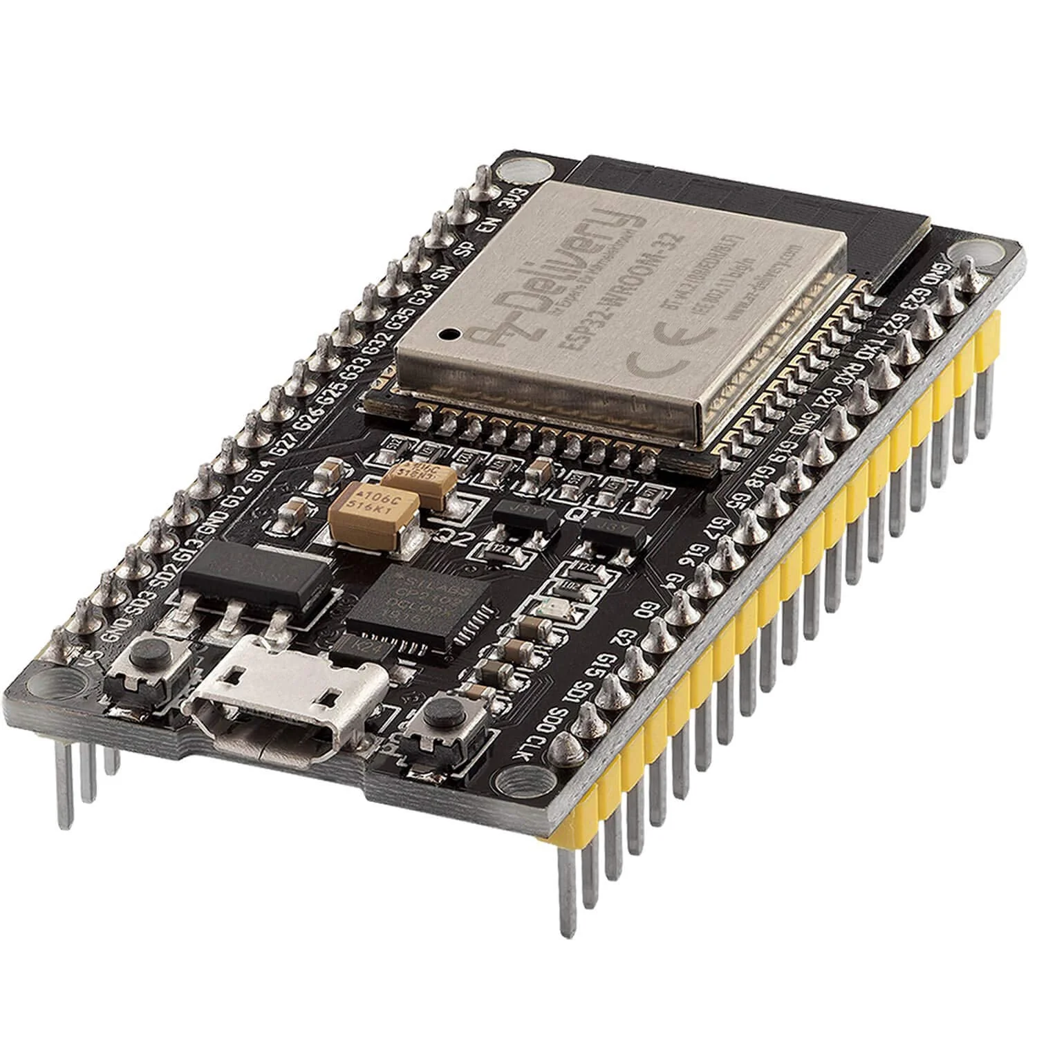
The ESP32 comes with a myriad of pins, each serving a specific purpose. The pinout is crucial for effective hardware design and interfacing with external devices.
>> Before diving into each pin category, the table below gives a quick-reference overview of which GPIO pins are safe to use, which require caution, and which should be avoided entirely in production designs.
| GPIO | Safe to Use | Notes |
|---|---|---|
| GPIO4, 5, 13, 14, 16, 17, 18, 19, 21, 22, 23, 25, 26, 27, 32, 33 | √ Yes | General-purpose; safe for LEDs, relays, sensors, I2C, SPI |
| GPIO0, 2, 12, 15 | !Caution | Strapping pins; must be at correct logic level during boot |
| GPIO1, 3 | ! Caution | UART0 TX/RX; avoid if Serial Monitor or USB flashing is needed |
| GPIO6, 7, 8, 9, 10, 11 | × Never | Connected to internal SPI flash; using them will crash or brick the device |
| GPIO34, 35, 36, 39 | ⚪ Input only | No internal pull-up/pull-down; cannot be used as outputs |
The ESP32 offers a range of General-Purpose Input/Output (GPIO) pins, allowing digital signals to be read or output. These pins are crucial for interfacing with sensors, actuators, and other digital devices.
The ESP32 has 34 GPIO pins in total numbered GPIO0 to GPIO39. Some GPIO pins are not accessible to users because they serve a special function. Examples of these are GPIO20 and GPIO28 to GPIO31. Moreover, GPIO37 and GPIO38 are not accessible on the development board. Also, take note that, GPIOs 34, 35, 36, and 39 are input-only pins.
One detail the pinout diagram does not show is the current capability of the GPIO pins. Each ESP32 GPIO can safely source or sink approximately 12 mA continuously, with an absolute maximum of 40 mA for short durations. The total current across all GPIO pins simultaneously should not exceed 1,200 mA. For practical purposes, this means a standard 5 mm LED with a 330 Ω series resistor is within the safe range for a single GPIO, but driving multiple LEDs, a relay coil, a motor, or any inductive load directly from a GPIO pin is not. Use a transistor, MOSFET, or dedicated driver IC between the GPIO and any load that draws more than 10 mA.
Interrupt pins are essential for handling external events promptly. The ESP32 provides specific pins that can be configured to trigger interrupts, enabling efficient event-driven programming.
Except for GPIO6 to GPIO11, all GPIO pins of the ESP32 can be used as an external interrupt. This means any change of state in any of these pins can trigger an interrupt provided that the attachInterrupt() function in Arduino has been enabled.
Strapping pins play a vital role during the device's boot process. They help set various configuration options, such as boot mode and flash voltage. Proper utilization of strapping pins is crucial for configuring the ESP32 at startup.
Strapping pins are sampled by the ESP32 during reset and power-on to determine the boot mode and flash voltage configuration. The strapping pins on the ESP32 are GPIO0, GPIO2, GPIO5, GPIO12, and GPIO15.
The statement that development board users do not need to worry about these pins is only partially true. On a standard devkit, the USB-TTL chip manages GPIO0 automatically during firmware upload. However, if you connect an external component — a sensor, a pull-down resistor, or even a long wire — to any strapping pin, it can pull that pin to an unexpected logic level during reset, causing the board to enter download mode instead of running your sketch, or to misconfigure the SPI flash voltage. GPIO12 is a particularly common offender: if it is pulled HIGH at boot on a WROOM-32 module, the flash voltage is set to 1.8 V instead of 3.3 V, which prevents the module from starting. Always use 10 kΩ or higher pull resistors on any external component attached to a strapping pin, and verify behavior at power-up rather than assuming the boot behavior observed during development will hold in the final product.
The ESP32 has two ADC units: ADC1 and ADC2, covering 18 channels total across GPIO32–GPIO39 (ADC1) and GPIO0, GPIO2, GPIO4, GPIO12–GPIO15, GPIO25–GPIO27 (ADC2).
There is a critical constraint that catches many designers off guard: ADC2 channels cannot be used while Wi-Fi is active. The Wi-Fi radio and ADC2 share internal circuitry, and when the radio is running, ADC2 reads return incorrect values or fail silently. If your project uses Wi-Fi and needs analog input, use ADC1 pins (GPIO32–GPIO39) exclusively. This is one of the most frequently reported issues in the ESP32 community and is not always obvious from pinout diagrams alone.
A second limitation worth noting is that the ESP32's ADC is non-linear near the ends of its range. Readings near 0 V and near 3.3 V are compressed and inaccurate. For measurements that require precision across the full voltage range, an external ADC connected via I²C or SPI will produce more reliable results.
Digital to Analog Converter (DAC) pins enable the generation of analog output signals. This feature is valuable in applications like audio synthesis and precision control systems. The ESP32 has two DAC pins which are GPIO25 and GPIO26.
The UART pins facilitate serial communication, supporting data exchange between the ESP32 and other devices. This is particularly useful for communication with sensors, displays, and other peripherals.
The ESP32 development board contains three UART interfaces. The transmit and receive pins for UART0 are GPI01 and GPIO3 respectively. For UART2, those pins are GPIO17 and GPIO16. The third interface, UART1 is reserved for USB-serial communication and is inaccessible to users.
The ESP32 Devkit includes touch-sensitive pins, enabling the implementation of touch interfaces. These pins are sensitive to touch and can be employed for various interactive applications. There are 10 GPIO pins for the touch sensor: GPIO4, GPIO0, GPIO2, GPIO15, GPIO13, GPIO12, GPIO14, GPIO27, GPIO33, and GPIO32.
For storage expansion, the ESP32 supports memory card interfacing through specific pins, making it suitable for projects that require additional data storage. Memory card pins are those labeled with VSPI in the pinout diagram above.
Pulse Width Modulation (PWM) pins are crucial for motor control and LED brightness modulation applications. The ESP32 offers a range of PWM pins for such purposes. The ESP32 has 16 PWM-capable pins. All of them are those that have wiggly lines in the pinout diagram above.
The ESP32's PWM motor control feature allows precise control of motors, making it ideal for robotics and other motor-driven projects.
Here is an example code in C/C++ that controls a motor, connected to GPIO5 of the ESP32, via PWM.
|
|
In this code, the motor speed gradually increases and decreases in a loop. You may need to adjust the GPIO pin number and the delays based on your specific motor and project requirements.
Here is another example PWM code using microPython for ESP32:
|
|
Inter-Integrated Circuit (I2C) pins facilitate easy communication between the ESP32 and other I2C-compatible devices, enabling a seamless connection to sensors, displays, and more.
The default hardware I2C pins for the ESP32 are GPIO22 (SCL) and GPIO21 (SDA). If using software I2C, any digital I/O pin can be used. You just need to specify which pin during the initialization of the Wire object.
|
|
For microPython, the syntax for SoftSPI is:
|
|
Here, the assigned SCL pin is GPIO5 and the SDA pin is GPIO4.
Serial Peripheral Interface (SPI) pins are vital for high-speed communication with devices like displays, flash memory, and other peripherals.
There are 4 SPI channels on the ESP32. Out of the four, only two are user accessible. These channels, referred to as HSPI and VSPI are mapped to I/O pins. The HSPI pins are GPIO13 (MOSI), GPIO12 (MISO), GPIO14 (SCLK), and GPIO15 (CS). For the VSPI, the pins are GPIO23 (MOSI), GPIO19 (MISO), GPIO18 (SCLK), and GPIO5 (CS).
In Arduino, the default SPI pins are those of VSPI. This means if you only do this,
|
|
The pins are already mapped to GPIO23, GPIO19, GPIO18, and GPIO5. If you want to use the other SPI, then do
|
|
You can also use the SPIClass to call whichever SPI channel you want. Here’s an example of using both SPI channels using SPIClass in the same code.
|
|
Real-Time Clock (RTC) pins are used for timekeeping functions. The ESP32 has dedicated pins to interface with an external RTC module. In the pinout diagram above, you can see which pins support RTC.
The ESP32 features a Hall sensor, making it suitable for applications requiring proximity or magnetic field detection. The hall sensor is hidden behind the metal lif of the ESP32. The hall sensor pin, however, is inaccessible as it is internally wired. You can read the hall sensor value using the following code:
|
|
I2S pins support high-quality audio communication, making the ESP32 suitable for audio applications like music playback and voice recognition.
As I2S output requires an analog signal, the DAC pins for the ESP32 can be used as I2S pins. If an external DAC is used, any available GPIO (digital) may be used for I2S applications.
The Pulse Counter Module allows counting pulses on specific pins, expanding the ESP32's capability for applications like event counting and speed measurement. All digital I/O pins can be assigned to a pulse counter module.
The ESP32's remote control module enables Infrared (IR) communication, making it compatible with various remote control devices. Similar to PCNT, all digital I/O pins can be assigned to a remote control module.
The enable pin is crucial for controlling the power supply to peripherals, allowing efficient power management.
The enable pin is the one labeled EN on the ESP32 development board. An EN button is also found near the microUSB port. Remember that when EN is pulled LOW, the ESP32 is disabled. When the EN pin is high or left as is, the ESP32 is enabled.
Certain pins can be utilized to enable automatic resetting of the ESP32, providing a convenient way to restart the device. One pin is the previously discussed EN pin which when pulled LOW disables the ESP32. Another pin is GPIO0, one of the strapping pins. If IO0 is held low during power-up or reset, the ESP32 goes into bootloader mode, which is useful for flashing new firmware.
Here’s an example Arduino code that resets the ESP32 every 5 seconds:
|
|
The most common cause is an external component pulling GPIO0 LOW during power-up or reset. GPIO0 is a strapping pin: when it reads LOW at boot, the ESP32 enters firmware download mode instead of executing the program in flash. Check whether any wiring connected to GPIO0, GPIO2, GPIO12, or GPIO15 — the four main strapping pins — could be pulling those pins to an unexpected logic level at the moment the chip resets. A sensor with its own pull-down, a passive component to ground, or even a long wire acting as an antenna can be enough. Move the sensor to a non-strapping GPIO and the issue will likely disappear immediately.
You are reading from an ADC2 pin while Wi-Fi is active. ADC2 and the Wi-Fi radio share internal circuitry on the ESP32, and the radio takes priority. When Wi-Fi initializes or transmits, ADC2 channels return incorrect values or fail to complete a conversion at all. The fix is to switch your analog input to an ADC1 pin — GPIO32, GPIO33, GPIO34, GPIO35, GPIO36, or GPIO39. ADC1 operates independently of the Wi-Fi radio and is unaffected by wireless activity. This is documented in Espressif's technical reference manual but is absent from most pinout diagrams, which is why it catches so many projects off guard.
The continuous safe limit is approximately 12 mA per GPIO pin, with a datasheet absolute maximum of 40 mA for brief durations. The total current across all GPIO pins simultaneously should not exceed 1,200 mA. In practical terms, a single LED with a current-limiting resistor is fine, but a relay coil, DC motor, solenoid, or multiple LEDs wired in parallel exceed what a GPIO can sustain safely. Use a transistor or MOSFET to switch higher-current loads, with the GPIO driving the gate or base rather than the load directly. Exceeding the GPIO current limit does not always cause an immediate failure — it can degrade the output driver over time and cause erratic behavior that is difficult to trace.
No. GPIO6 through GPIO11 are permanently connected to the internal SPI flash memory on all ESP-WROOM-32 and ESP-WROVER modules. Using these pins for any external purpose will interfere with flash read and write operations, causing random crashes, failed boots, or in some cases a bricked device that cannot be reflashed. Some 38-pin development boards expose these pins on their headers, which makes them appear usable — they are not. Leave GPIO6–GPIO11 unconnected and never assign them in firmware.
If your board uses an ESP32-WROVER module rather than a WROOM module, GPIO16 and GPIO17 are internally connected to the PSRAM chip and are not available for external use, even though they appear on some board silkscreens. The WROVER module integrates 8 MB of PSRAM for applications that need more RAM — camera buffers, audio processing, large web responses — and those two pins are the PSRAM's interface lines. Check which module your development board is built on: if the module label says WROVER, treat GPIO16 and GPIO17 as unavailable. If it says WROOM, those pins are free for general use as UART2 TX and RX.
The ESP32's pinout is a roadmap to its vast capabilities. Effectively leveraging the diverse functionalities of its pins opens up a world of possibilities for embedded systems, IoT applications, and beyond. As you embark on your ESP32 projects, a solid understanding of the pinout configuration will be your guiding light, empowering you to unlock the full potential of this remarkable microcontroller.
The ESP32 pinout is dense, and the gap between a working prototype and a reliable product often comes down to the pin decisions that diagrams do not highlight: which ADC channels conflict with Wi-Fi, which strapping pins will cause intermittent boot failures under load, and what current limit a GPIO can safely sustain. Keeping the safe-pin reference table above close when laying out a new schematic avoids most of the common mistakes.
For next steps, the ESP32 BLE Control guide covers Bluetooth Low Energy implementation on the same hardware, and the Getting Started with ESP32 guide covers the full development environment setup if you are working with a new board. When you are ready to move from breadboard to a custom PCB, NextPCB's PCB prototype service supports the impedance control and DFM review that ESP32 RF designs require.
- ESP32 BLE(Bluetooth Low Energy) Control in Arduino IDE
- Free Worldwide Shipping on Over 600,000 Electronics Components with HQ Online
- Free PCB Assembly Offer is Now Live: Experience Reliable PCB Assembly from HQ NextPCB
Still, need help? Contact Us: support@nextpcb.com
Need a PCB or PCBA quote? Quote now


 Surface