
 Surface


Julia Wu - Senior Sales Engineer at NextPCB.com

 NextPCB Capabilities
Printed Circuit Boards
NextPCB Capabilities
Printed Circuit Boards
 PCB Assembly
 Layer Buildup
 SMD-Stencils
 PCB Design-Aid & Layout
 Mechanics
 Quality
 Drills & Throughplating
 Factory & Certificate
 PCB Assembly Factory Show
Certificate
PCB Assembly Factory Show
Certificate
Support Team
Feedback:
support@nextpcb.com


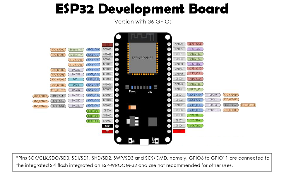
The ESP32 is one of the most versatile microcontroller modules available to engineers and makers today. Developed by Espressif Systems, it integrates Wi-Fi and Bluetooth connectivity into a compact, energy-efficient package — making it an ideal platform for IoT applications, wearable electronics, and home or office automation systems.
What distinguishes the ESP32 from earlier chips such as the ESP8266 is its dual-core Xtensa processor, which enables two independent tasks to execute concurrently. For example, one core can handle sensor polling while the other manages data transmission to a cloud platform — a meaningful advantage in real-world embedded deployments. The processor clock is software-configurable from 80 MHz up to 240 MHz, giving developers direct control over the trade-off between compute performance and power draw. The chip also supports data rates up to 150 Mbps with up to 22 dBm PA output power, helping maximize wireless range.
This guide covers ten beginner-friendly projects designed to build familiarity with the ESP32’s GPIO system, analog input channels, communication buses, display peripherals, and cloud integration using the Blynk IoT platform.
The following table summarizes the core electrical and radio parameters of the standard ESP32 module:
| Parameter | Value |
|---|---|
| Supply Voltage | 2.2 V – 3.6 V |
| Receive / Transmit Current | 80 mA |
| Integrated SRAM | 520 KB |
| Flash Memory | 4 MB (typical) |
| GPIO Count | 30 |
| Wi-Fi Protocol | 802.11 b/g/n/d/e/i |
| Frequency Band | 2.4 GHz |
| RF Sensitivity | −98 dBm |
| Output Power | 16.5 dBm |
| Serial Interfaces | I²C, I²S, SPI, UART |
| Operating Temperature | −40°C to +85°C |
| Antenna | On-board PCB antenna |
| Connectivity | Hybrid Wi-Fi & Bluetooth |
Beyond basic GPIO, the ESP32 provides a rich set of built-in peripherals:
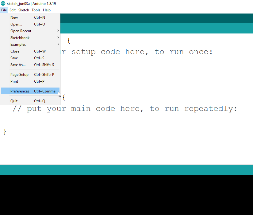
The ESP32 board package is not bundled with the default Arduino IDE installation and must be added through the Boards Manager. The process takes under five minutes on a typical internet connection.
Step 1: Open Arduino IDE and go to File → Preferences.
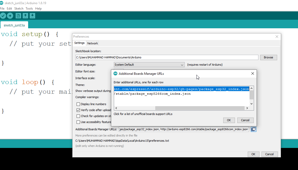
Step 2: In the Additional Boards Manager URLs field, paste the following endpoint:
https://raw.githubusercontent.com/espressif/arduino-esp32/gh-pages/package_esp32_index.json
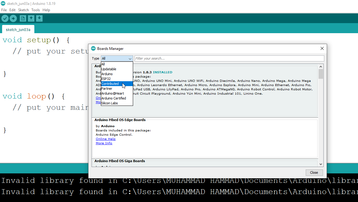
Step 3: Navigate to Tools → Board → Boards Manager.
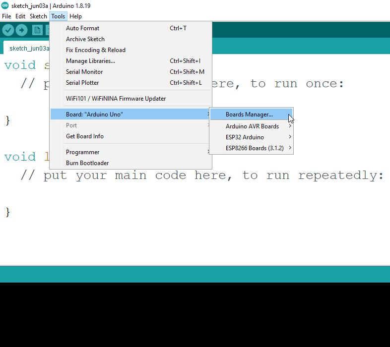
Step 4: Set the filter to Contributed, search for “ESP32”, and click Install.
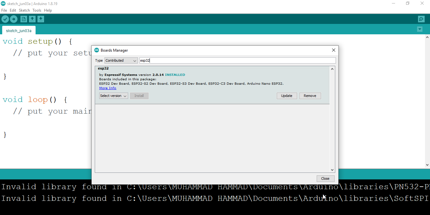
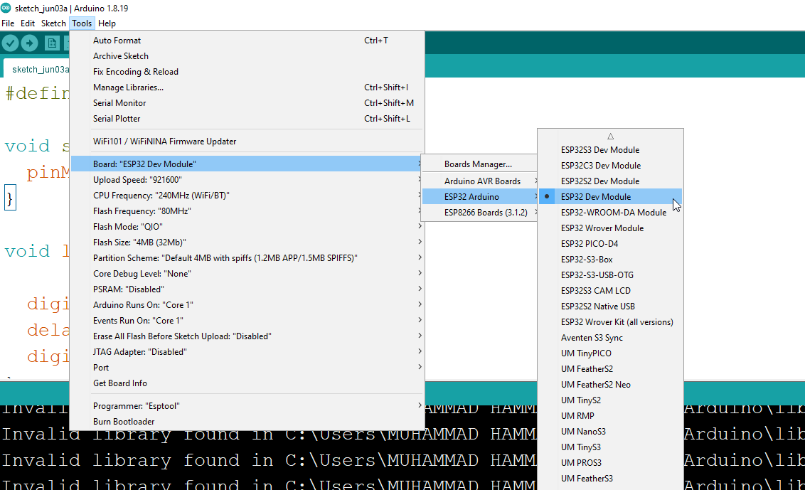
Once installed, select ESP32 Dev Module from the board list and choose the correct COM port before uploading any sketch.
The LED blink sketch is the standard first program for any new microcontroller setup. On most ESP32 development boards, the onboard LED is connected to GPIO 5 — however some variants wire it to GPIO 2 or another pin. Verify this for your specific board before uploading.
Select ESP32 Dev Module in the Tools menu, assign the correct port, then upload the following:
#define LED_PIN 5

void setup() {
  pinMode(LED_PIN, OUTPUT);
}

void loop() {
  digitalWrite(LED_PIN, HIGH);
  delay(1000);
  digitalWrite(LED_PIN, LOW);
  delay(1000);
}
This project demonstrates how to drive any digital output pin on the ESP32. An external LED wired through a current-limiting resistor gives visual confirmation that the GPIO is functioning correctly.
Wiring:

#define LED_PIN 4

void setup() {
  pinMode(LED_PIN, OUTPUT);
}

void loop() {
  digitalWrite(LED_PIN, HIGH);
  delay(1000);
  digitalWrite(LED_PIN, LOW);
  delay(1000);
}
The logic is identical to Project 1 — only the pin number differs. Try reassigning the constant to different GPIO numbers to build an intuitive understanding of the ESP32’s output mapping. Any valid output-capable GPIO will work.
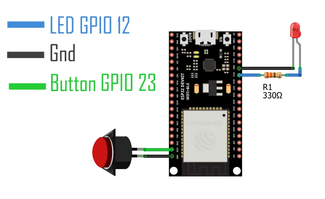
Reading a push button introduces digital input handling and the use of the ESP32’s internal pull-up resistor, which eliminates the need for an external resistor on the input line.
Wiring:
int ledPin = 12;
int btnPin = 23;

void setup() {
  pinMode(ledPin, OUTPUT);
  pinMode(btnPin, INPUT_PULLUP);
}

void loop() {
  if (digitalRead(btnPin) == HIGH) {
    digitalWrite(ledPin, HIGH);
  }
  if (digitalRead(btnPin) == LOW) {
    digitalWrite(ledPin, LOW);
  }
}
With INPUT_PULLUP active, the pin reads HIGH by default and transitions to LOW when the button shorts it to ground. No external pull-up resistor is required.
The ESP32’s 12-bit ADC maps analog voltages from 0 to 3.3 V into integer values ranging from 0 to 4095. A potentiometer provides a simple, manually adjustable analog signal for testing this functionality.
Wiring:
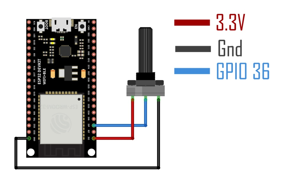
int potPin   = A0;
int potValue = 0;

void setup() {
  Serial.begin(115200);
  pinMode(potPin, INPUT);
}

void loop() {
  potValue = analogRead(potPin);
  Serial.print("Pot Value: ");
  Serial.println(potValue);
  delay(500);
}
Open the Serial Monitor at 115200 baud after uploading. Rotate the potentiometer knob and observe the raw ADC values updating in real time.
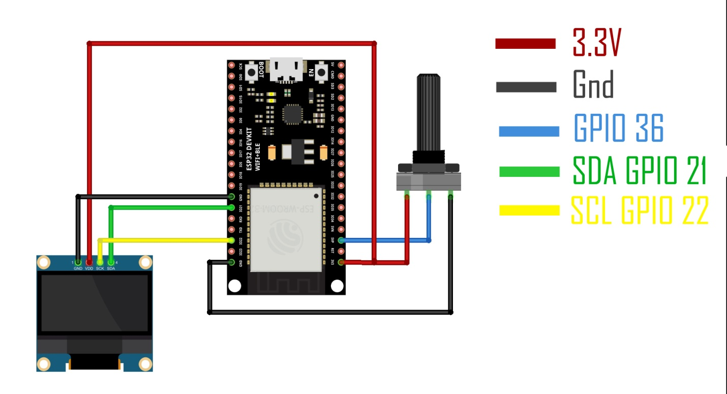
This project routes the potentiometer readings from the Serial Monitor to a 128×64 pixel I²C OLED display, making the output visible without a connected computer.
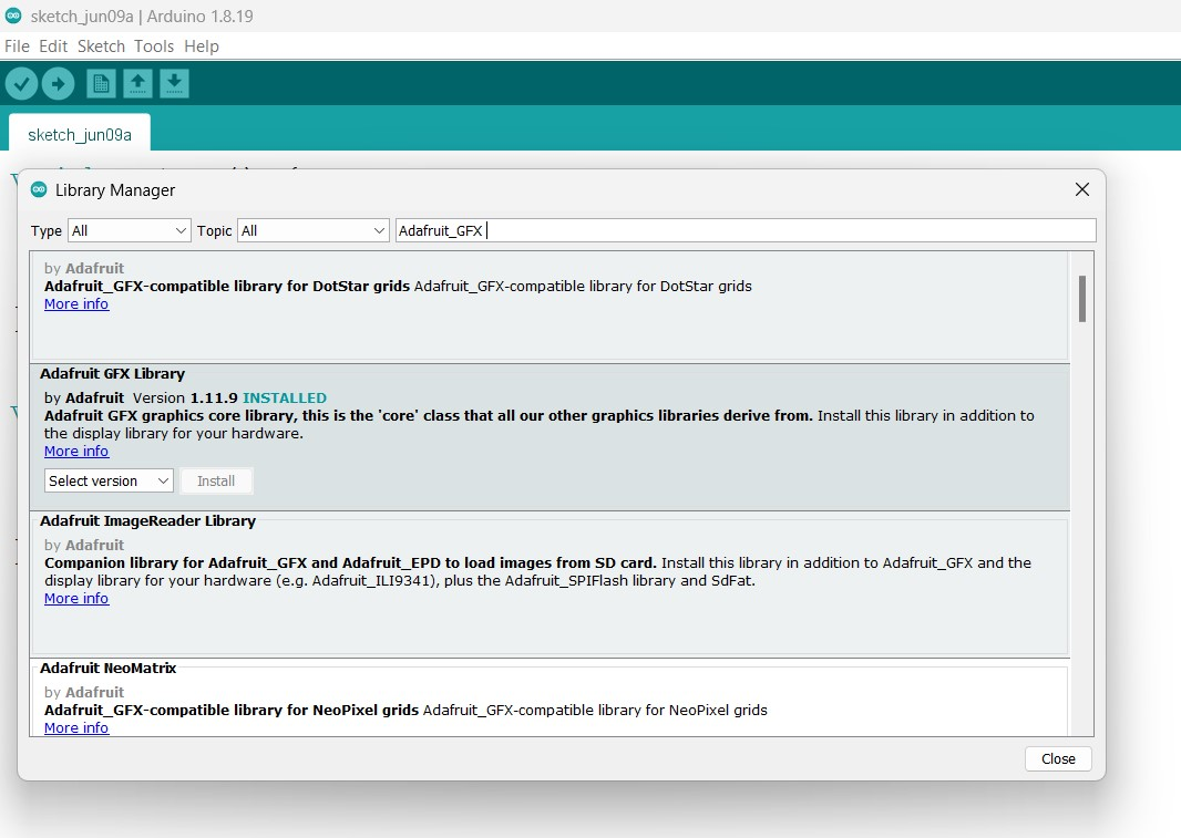
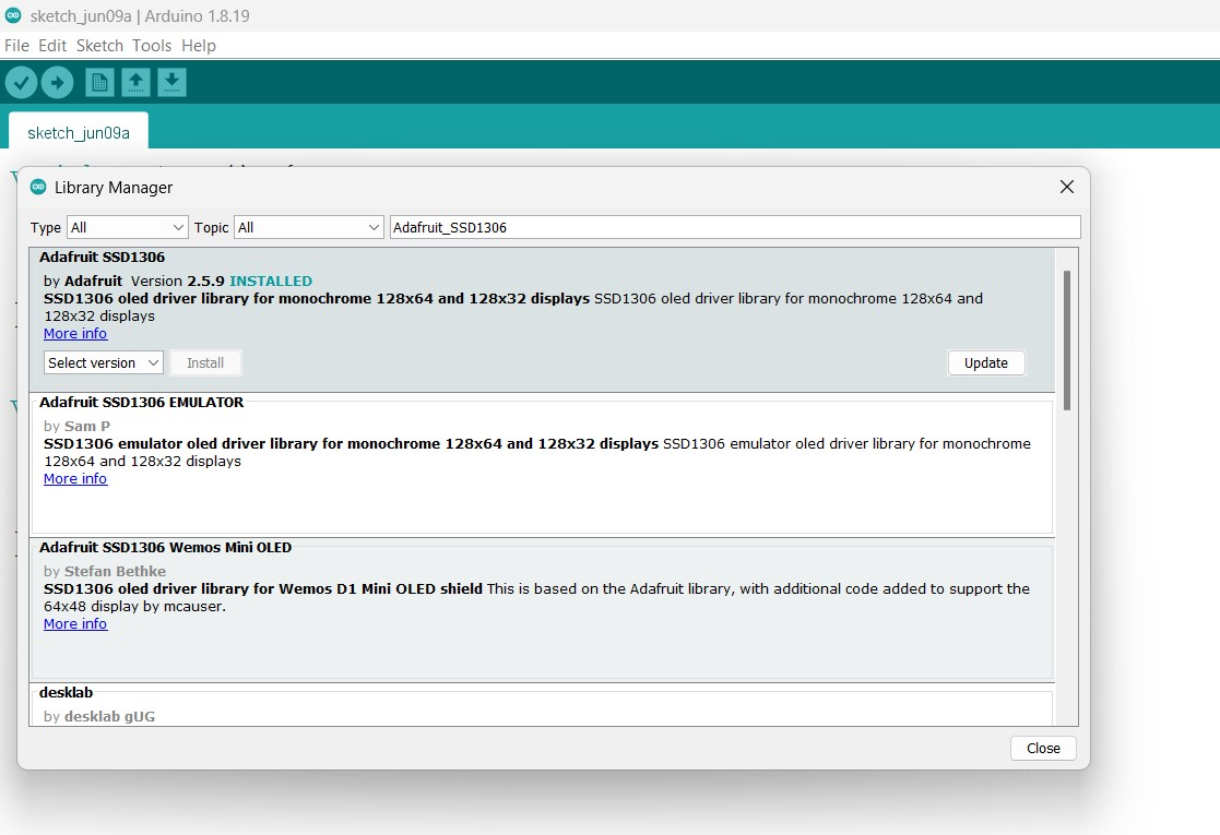
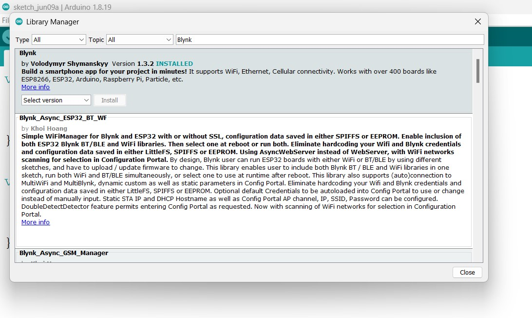
Required libraries: Adafruit GFX, Adafruit SSD1306, SimpleTimer (bundled with the Blynk library package)
Wiring (potentiometer): same as Project 4
Wiring (SSD1306 OLED):
Install the Adafruit GFX library via Sketch → Include Library → Manage Libraries:
#include
#include
#include
#include

#define SCREEN_WIDTH     128
#define SCREEN_HEIGHT     64
#define OLED_RESET        -1
#define REPORTING_PERIOD_MS 2000

Adafruit_SSD1306 display(SCREEN_WIDTH, SCREEN_HEIGHT, &Wire, OLED_RESET);
SimpleTimer timer;

int potPin  = A0;
int potVal  = 0;
uint32_t tsLastReport = 0;

void getSendData() {
  display.clearDisplay();
  display.setTextSize(3);
  display.setCursor(0, 0);
  display.print("POT:");
  display.setTextSize(4);
  display.setCursor(0, 30);
  display.print(potVal);
  display.display();
}

void setup() {
  Serial.begin(115200);
  pinMode(potPin, INPUT);
  display.begin(SSD1306_SWITCHCAPVCC, 0x3C);
  display.clearDisplay();
  display.setTextColor(WHITE);
  timer.setInterval(2000L, getSendData);
}

void loop() {
  timer.run();
  if (millis() - tsLastReport > REPORTING_PERIOD_MS) {
    potVal = analogRead(potPin);
    tsLastReport = millis();
  }
}
A 16-column, 2-row LCD with an I²C backpack module is a widely available alternative to the OLED. It uses the same SDA/SCL pins as the SSD1306 and supports text output without the need for complex graphics libraries.
Wiring:
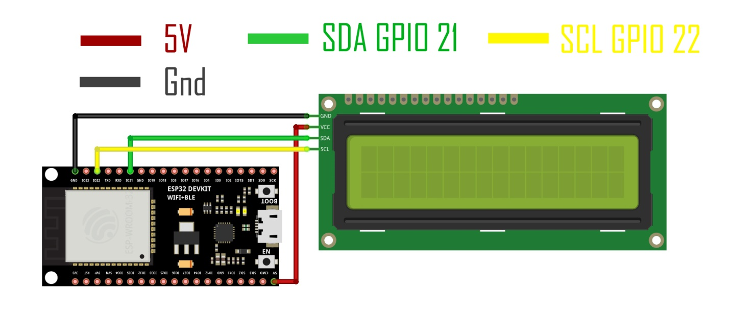
Install the LiquidCrystal_I2C library, then upload the following sketch. If the display does not respond, run an I²C scanner sketch to confirm your module’s address — common alternatives to 0x27 include 0x3F.
#include
#include

LiquidCrystal_I2C lcd(0x27, 16, 2);

void setup() {
  lcd.init();
  lcd.backlight();
  lcd.home();
}

void loop() {
  lcd.clear();
  lcd.print("NextPCB");
  delay(1000);

  lcd.setCursor(0, 1);
  for (int i = 0; i <= 5; i++) {
    lcd.print(i);
    delay(500);
  }

  lcd.clear();
  lcd.setCursor(0, 0);
  lcd.print("NextPCB");
  for (int i = 0; i <= 5; i++) {
    lcd.setCursor(0, 1);
    lcd.print(i);
    delay(500);
  }

  lcd.noDisplay();
  delay(500);
  lcd.display();
  delay(500);
}
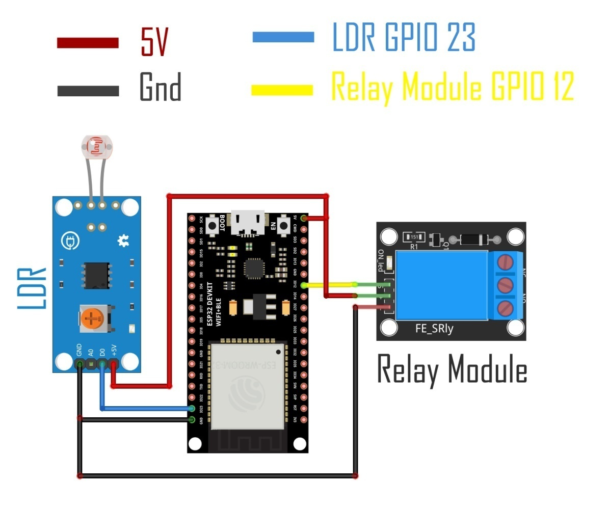
An LDR (light-dependent resistor) module outputs a digital HIGH or LOW signal relative to a light threshold set by its onboard trimmer potentiometer. Combined with a single-channel relay, this creates a simple automatic switching circuit — turning a connected load on when darkness is detected and off when sufficient light returns.
Wiring:
int ldrPin   = 23;
int relayPin = 12;

void setup() {
  pinMode(ldrPin,   INPUT);
  pinMode(relayPin, OUTPUT);
}

void loop() {
  if (digitalRead(ldrPin) == HIGH) {
    digitalWrite(relayPin, HIGH);
    delay(3000);
  }
  if (digitalRead(ldrPin) == LOW) {
    digitalWrite(relayPin, LOW);
  }
}
The 3-second delay on the HIGH branch prevents the relay from chattering in marginal lighting conditions. Adjust the LDR module’s onboard potentiometer to calibrate the switching threshold for your environment.
The HC-SR04 ultrasonic sensor determines distance by emitting a 40 kHz pulse and timing the return echo. Pairing it with the SSD1306 OLED produces a self-contained rangefinder with a visible numeric readout.
Wiring:
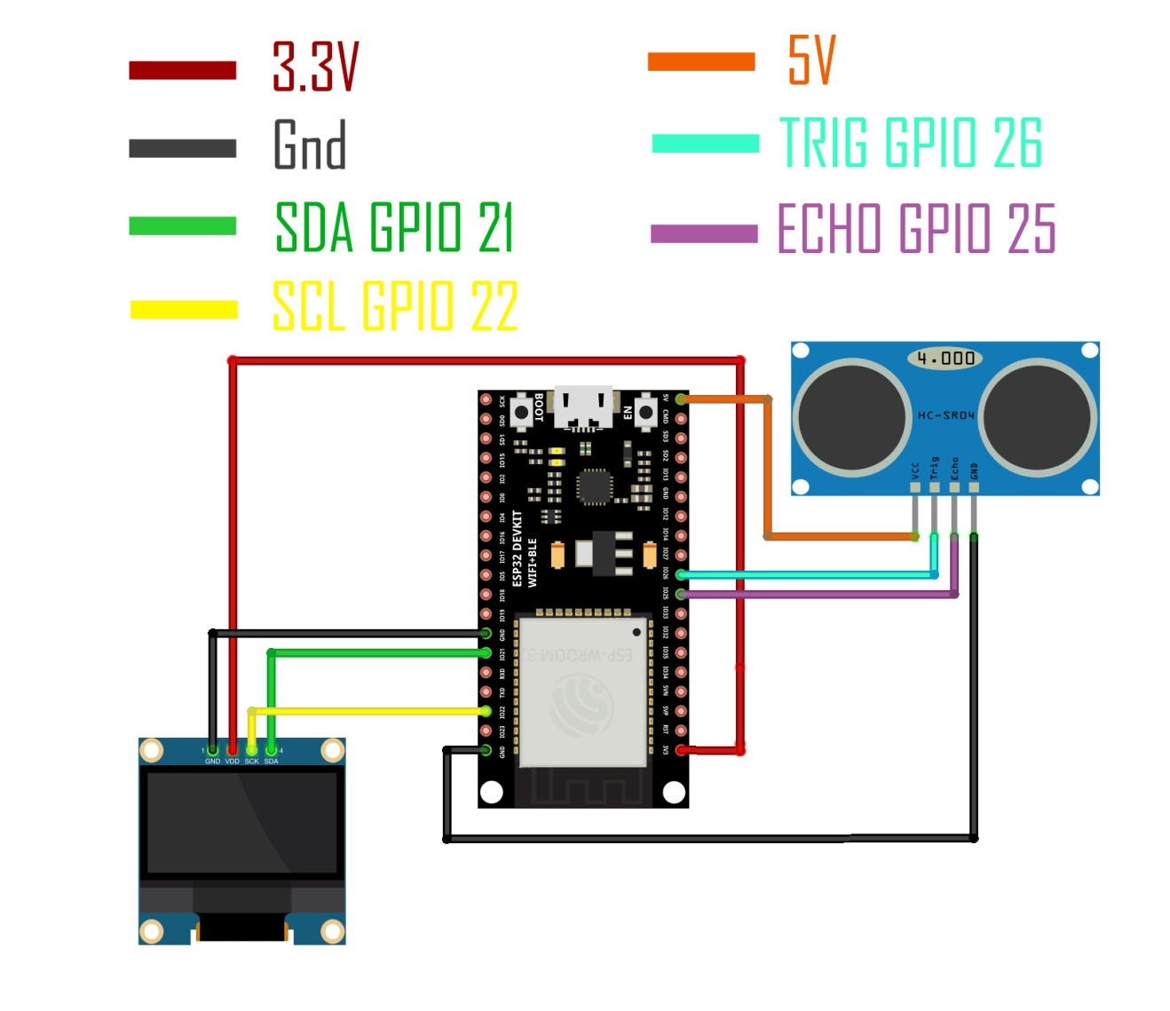
The core distance calculation uses the speed of sound (0.034 cm/µs) and divides by 2 to account for the round-trip travel time:
long duration   = pulseIn(echoPin, HIGH);
float distanceCm = duration * 0.034 / 2;
Feed this result into the Adafruit_SSD1306 display methods from Project 5 to render the measured distance on the OLED in centimeters.
The DHT21 (also labelled AM2301) is a factory-calibrated sensor that reports both ambient temperature and relative humidity over a single digital data line. It is a reliable choice for environmental monitoring in enclosures, greenhouses, or server rooms.
Wiring:
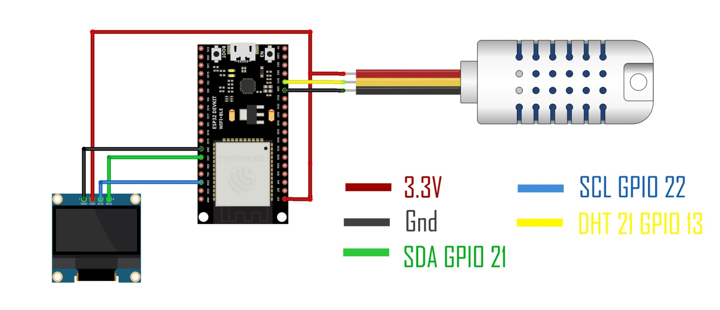
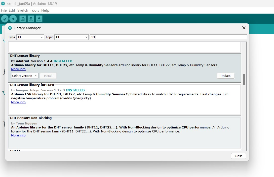
Install the DHT sensor library by Adafruit from the Library Manager:
#include
#include
#include

#define DHTPIN  13
#define DHTTYPE DHT21

DHT dht(DHTPIN, DHTTYPE);

#define SCREEN_WIDTH  128
#define SCREEN_HEIGHT  64
#define OLED_RESET     -1
Adafruit_SSD1306 display(SCREEN_WIDTH, SCREEN_HEIGHT, &Wire, OLED_RESET);

float hum  = 0;
float temp = 0;

void setup() {
  Serial.begin(9600);
  dht.begin();
  display.begin(SSD1306_SWITCHCAPVCC, 0x3C);
  delay(2000);
  display.clearDisplay();
  display.setTextColor(WHITE);
}

void loop() {
  hum  = dht.readHumidity();
  temp = dht.readTemperature();

  Serial.print("Humidity: ");    Serial.print(hum);
  Serial.print("%, Temp: ");     Serial.print(temp);
  Serial.println(" C");

  display.clearDisplay();
  display.setTextSize(2);
  display.setCursor(0, 10);
  display.print(temp);
  display.print((char)247);
  display.print("C");
  display.setCursor(0, 30);
  display.print("H:" + String(hum) + "%");
  display.display();
}
This final project ties everything together: a DS18B20 waterproof one-wire temperature sensor feeds readings to both an SSD1306 OLED display and the Blynk cloud platform, while a relay can be toggled remotely from a smartphone in real time.
Wiring:
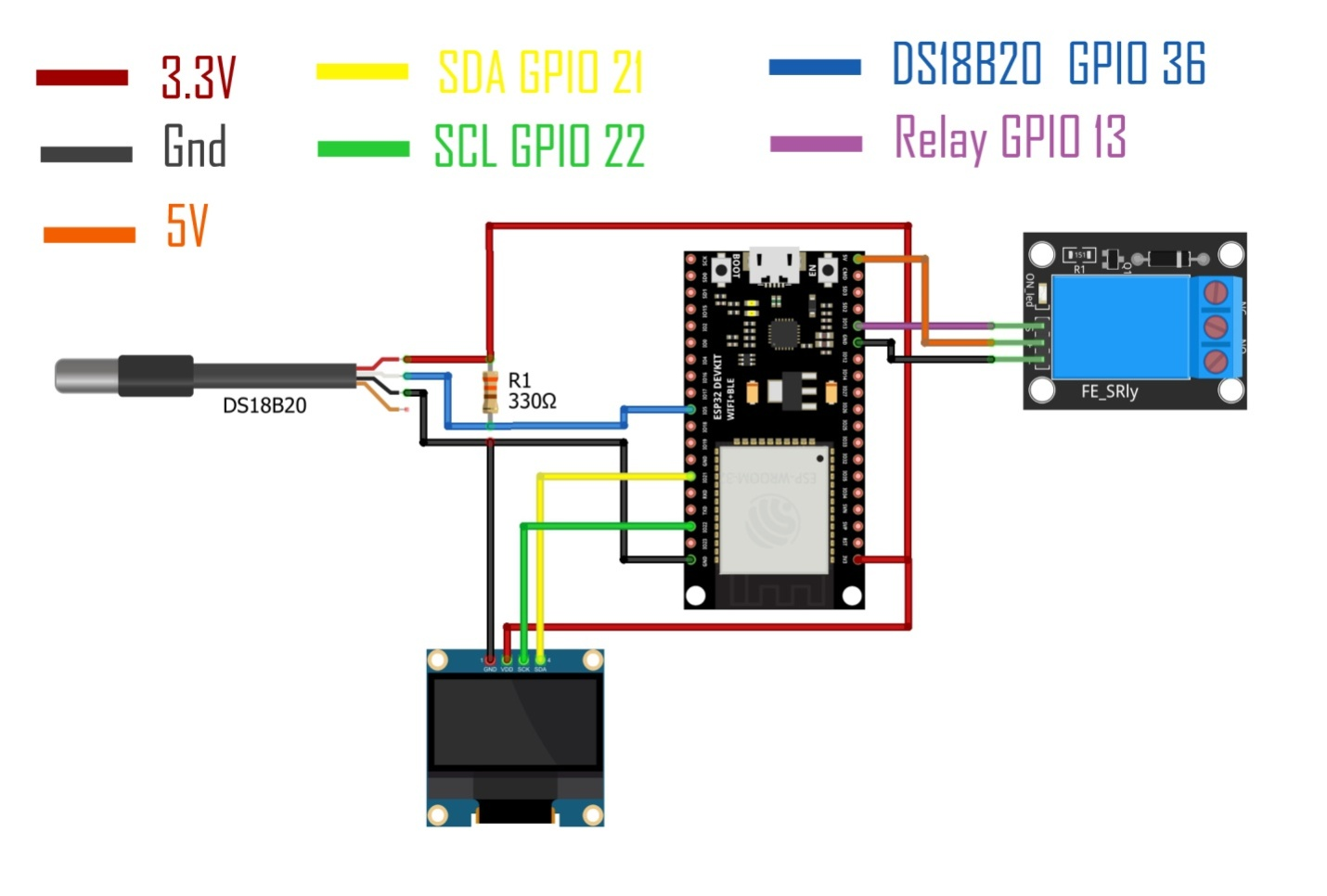
Required libraries: Blynk, OneWire, DallasTemperature, Adafruit GFX, Adafruit SSD1306, SimpleTimer
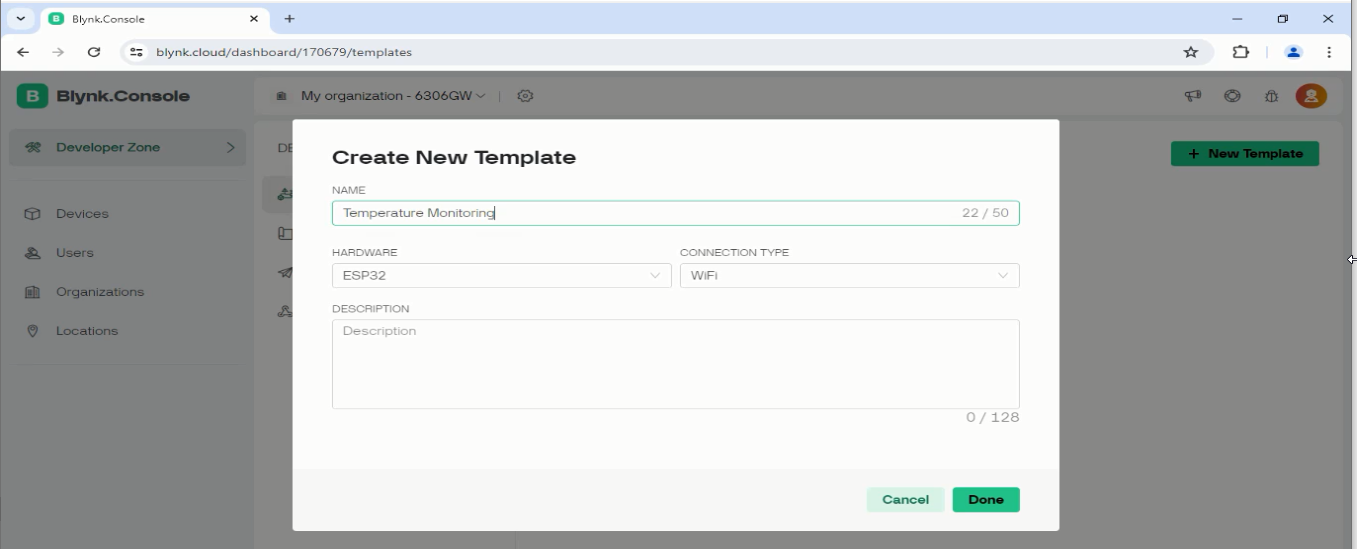
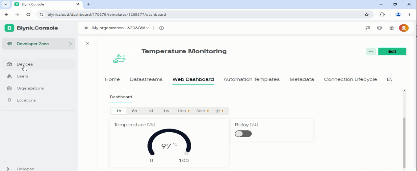
Log in to blynk.io and complete the following steps:
1. Create a template named “Temperature Monitoring” and click Done.
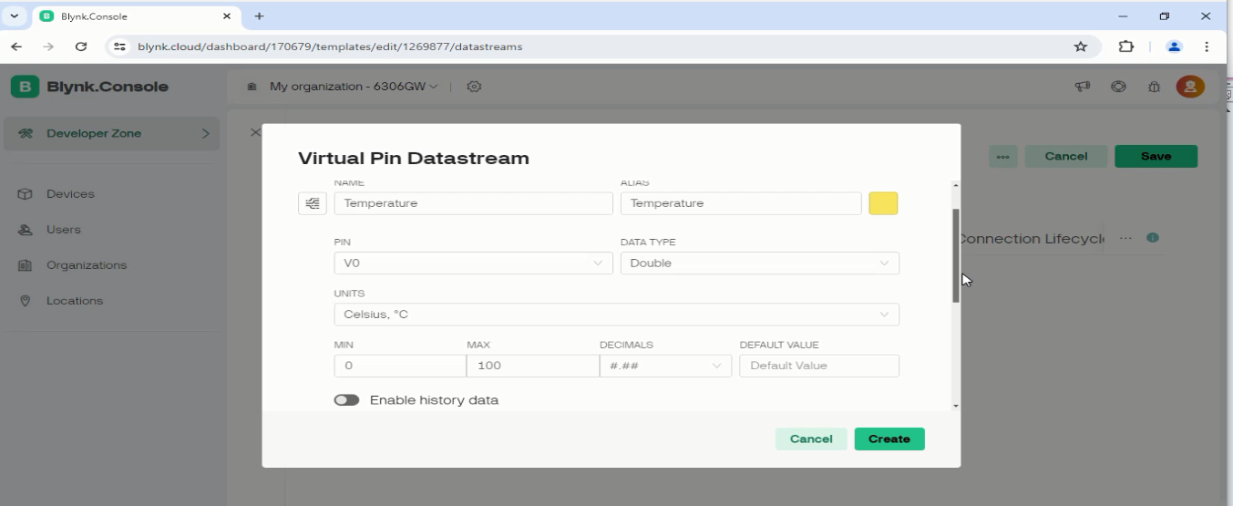
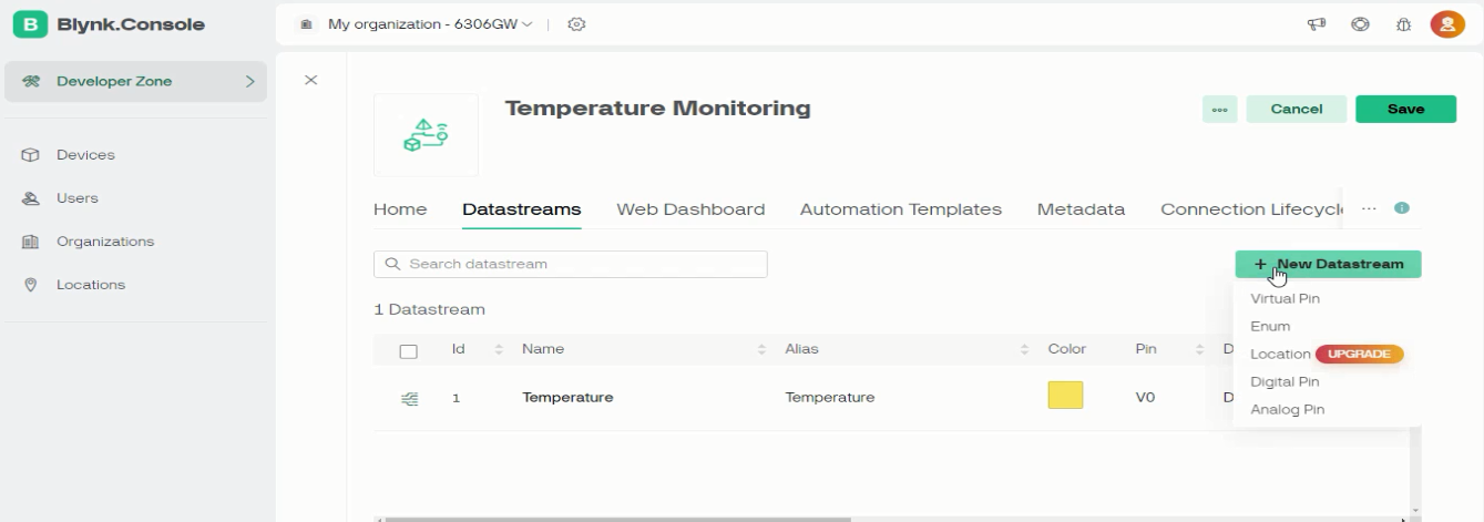
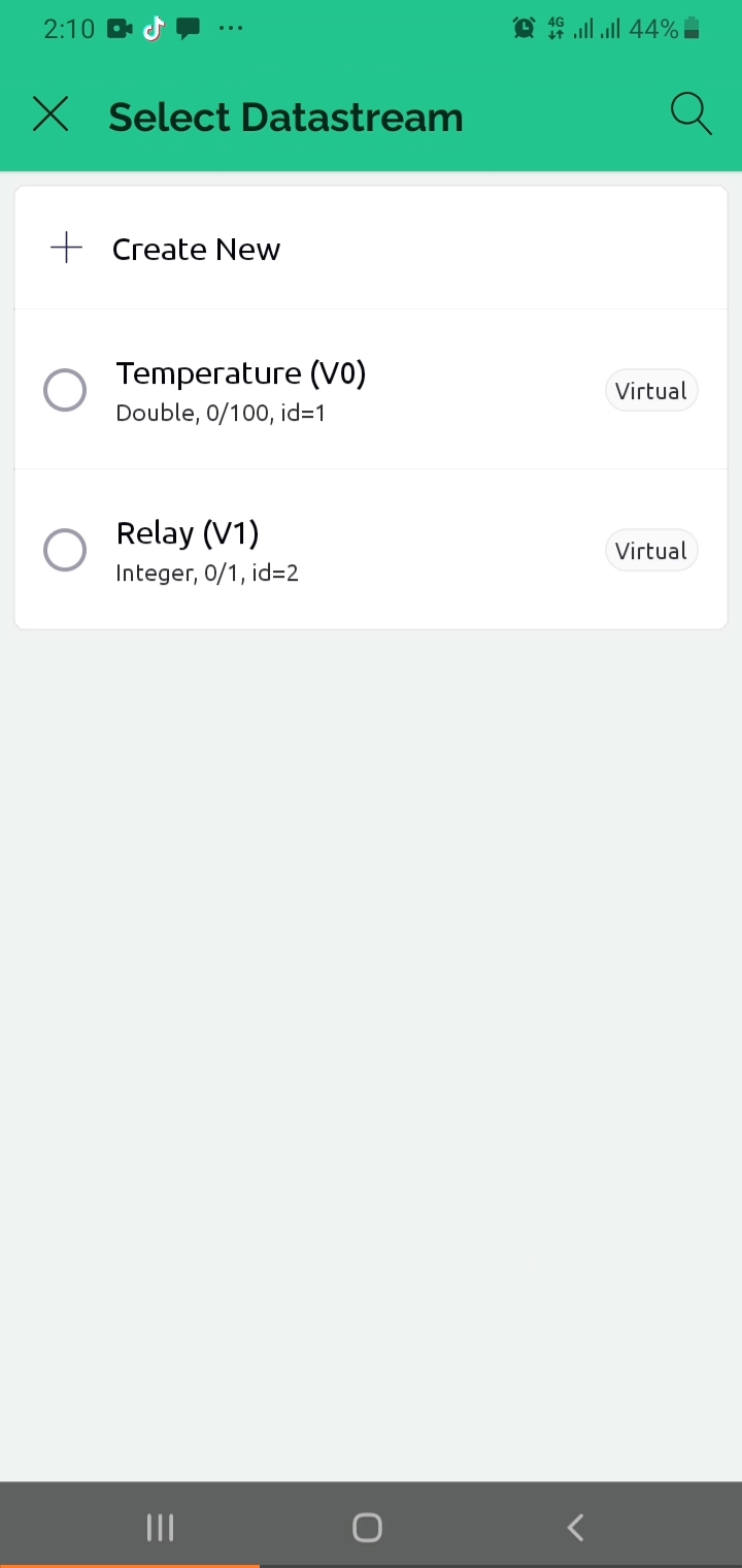
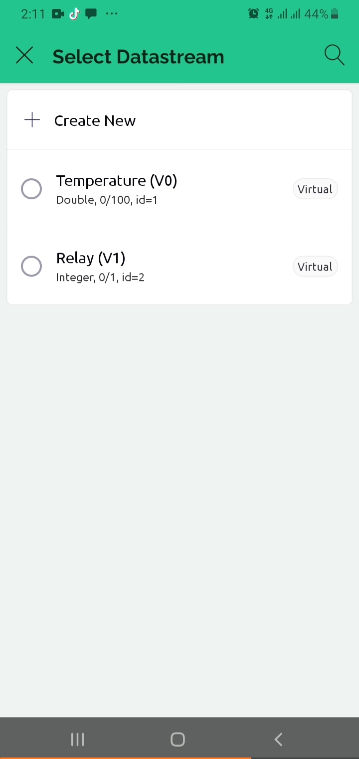
2. Add Datastream V0 (Virtual Pin, float, for temperature).
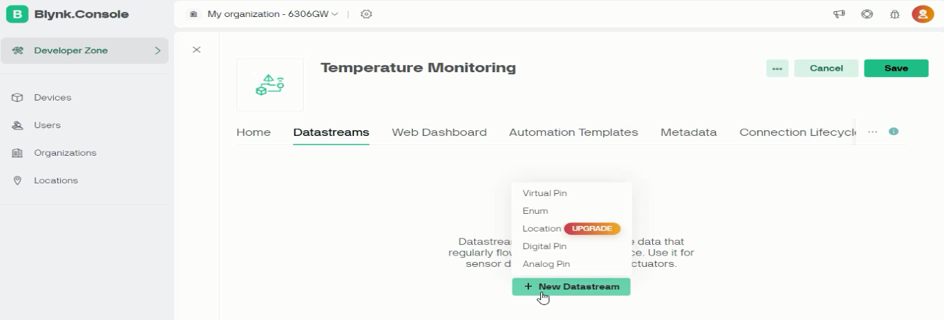
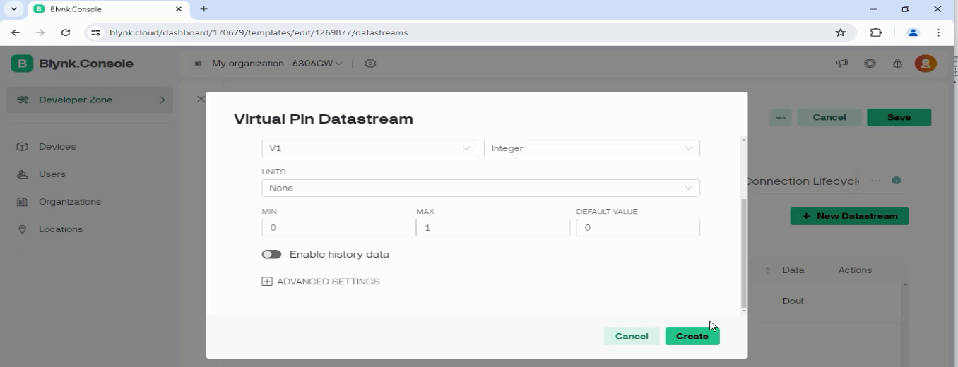
3. Add Datastream V1 (Virtual Pin, integer 0–1, for relay control).
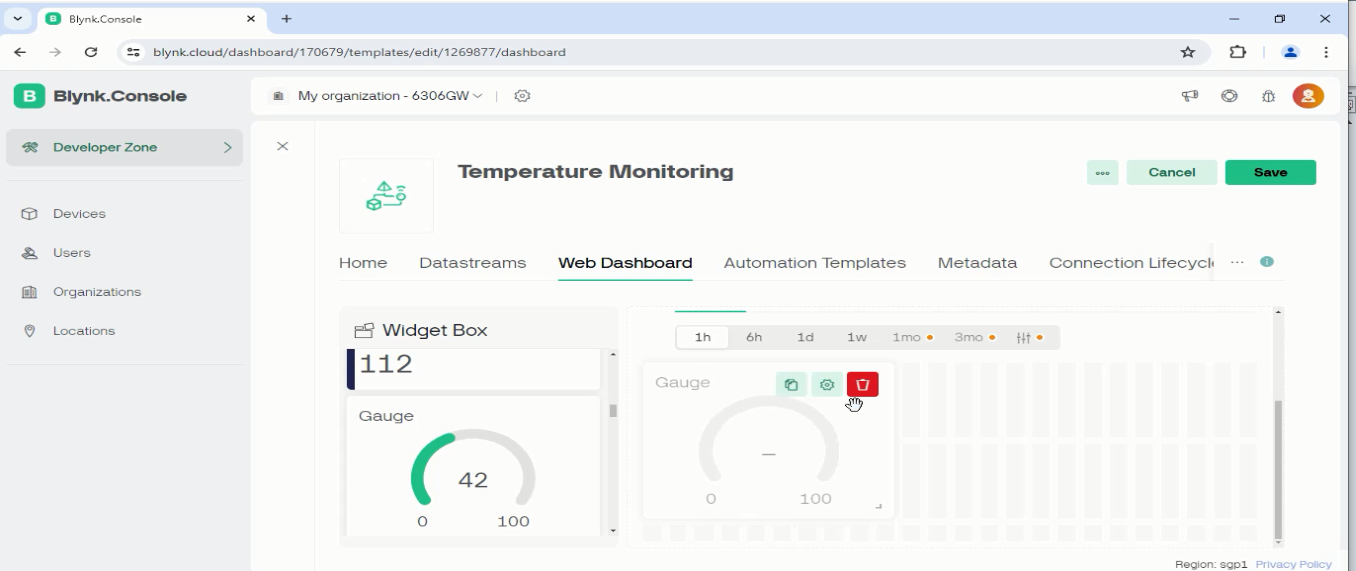
4. Build the Web Dashboard — add a Gauge widget and link it to V0, then add a Switch widget and link it to V1.
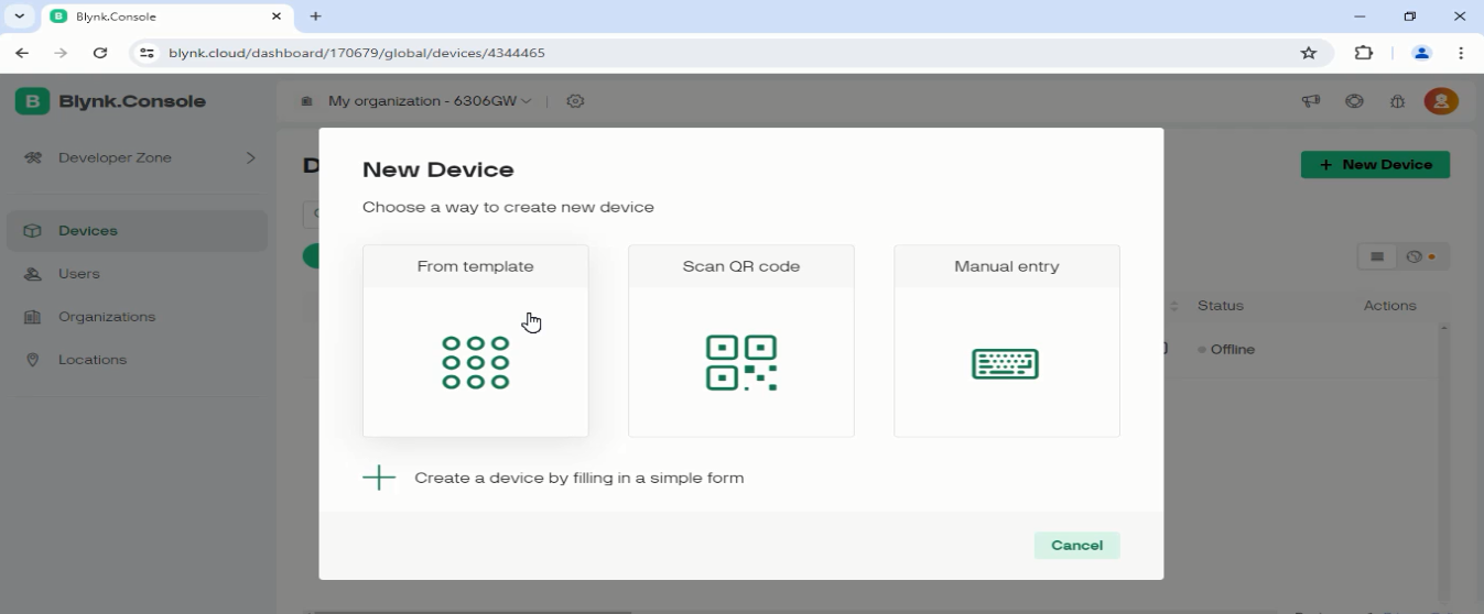
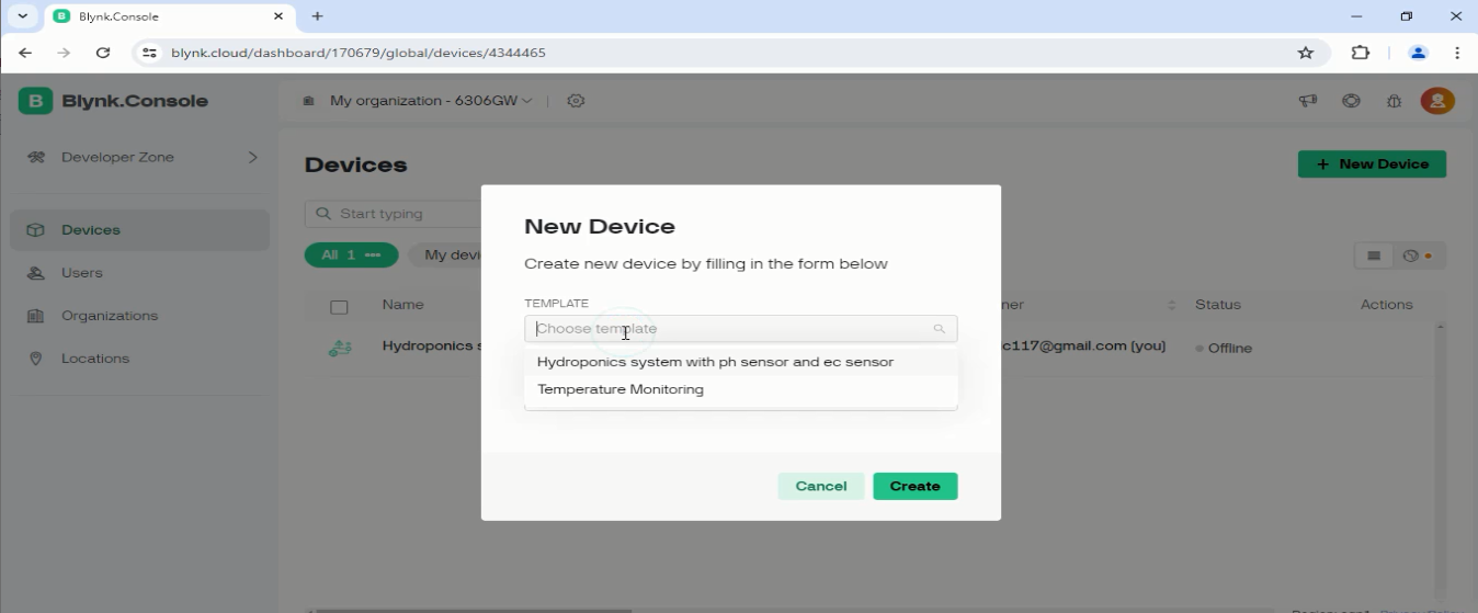
5. Add a Device from the template and copy the generated credentials.
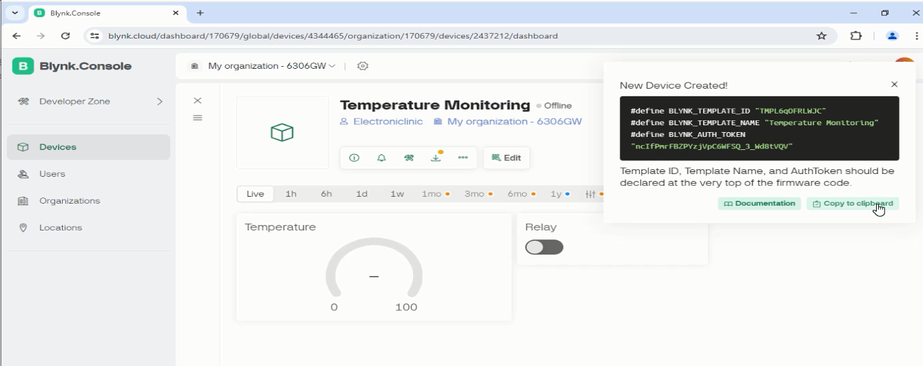
Paste those credentials into the sketch:
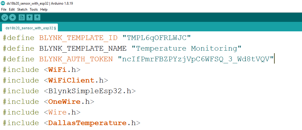
#define BLYNK_TEMPLATE_ID   "YOUR_TEMPLATE_ID"
#define BLYNK_TEMPLATE_NAME "Temperature Monitoring"
#define BLYNK_AUTH_TOKEN    "YOUR_AUTH_TOKEN"

#include
#include
#include
#include
#include
#include
#include
#include
#include

char auth[] = BLYNK_AUTH_TOKEN;
char ssid[] = "YOUR_WIFI_SSID";
char pass[] = "YOUR_WIFI_PASSWORD";

int relayPin = 13;
SimpleTimer timer;

#define SCREEN_WIDTH  128
#define SCREEN_HEIGHT  64
#define OLED_RESET     -1
Adafruit_SSD1306 display(SCREEN_WIDTH, SCREEN_HEIGHT, &Wire, OLED_RESET);

namespace pin  { const byte ds18b20 = 5; }
namespace sensor { float waterTemp = 0; }

OneWire oneWire(pin::ds18b20);
DallasTemperature sensors(&oneWire);

void displayValue() {
  sensors.requestTemperatures();
  sensor::waterTemp = sensors.getTempCByIndex(0);
  Serial.print("Temperature: ");
  Serial.println(sensor::waterTemp, 2);

  display.clearDisplay();
  display.setTextSize(2);
  display.setCursor(0, 10);
  display.print(sensor::waterTemp);
  display.print((char)247);
  display.print("C");
  display.display();

  Blynk.virtualWrite(V0, sensor::waterTemp);
}

BLYNK_WRITE(V1) {
  int pinValue = param.asInt();
  digitalWrite(relayPin, pinValue);
}

void setup() {
  Serial.begin(115200);
  sensors.begin();
  Blynk.begin(auth, ssid, pass);
  display.begin(SSD1306_SWITCHCAPVCC, 0x3C);
  delay(2000);
  display.clearDisplay();
  display.setTextColor(WHITE);
  pinMode(relayPin, OUTPUT);
  digitalWrite(relayPin, LOW);
  timer.setInterval(1000L, displayValue);
}

void loop() {
  Blynk.run();
  timer.run();
}
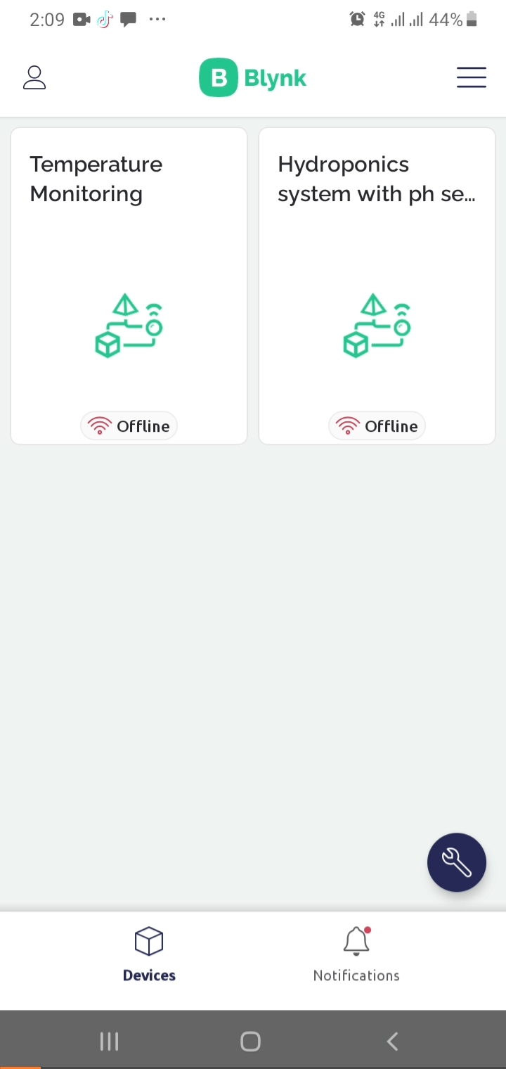
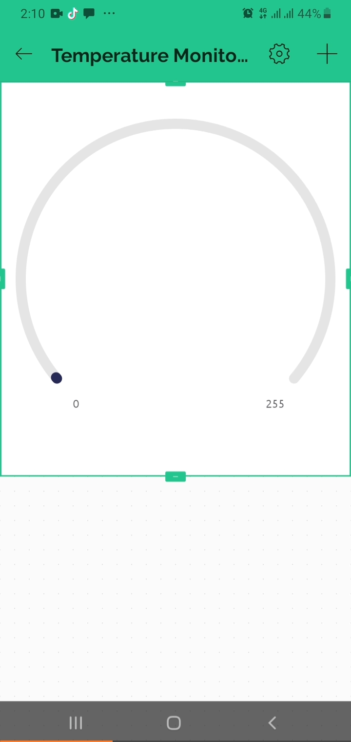
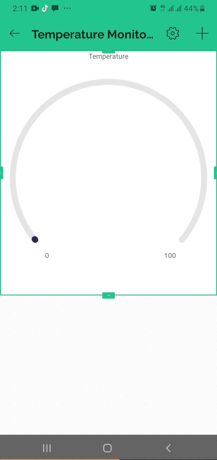
Open the Blynk IoT app on your smartphone and select the Temperature Monitoring project:
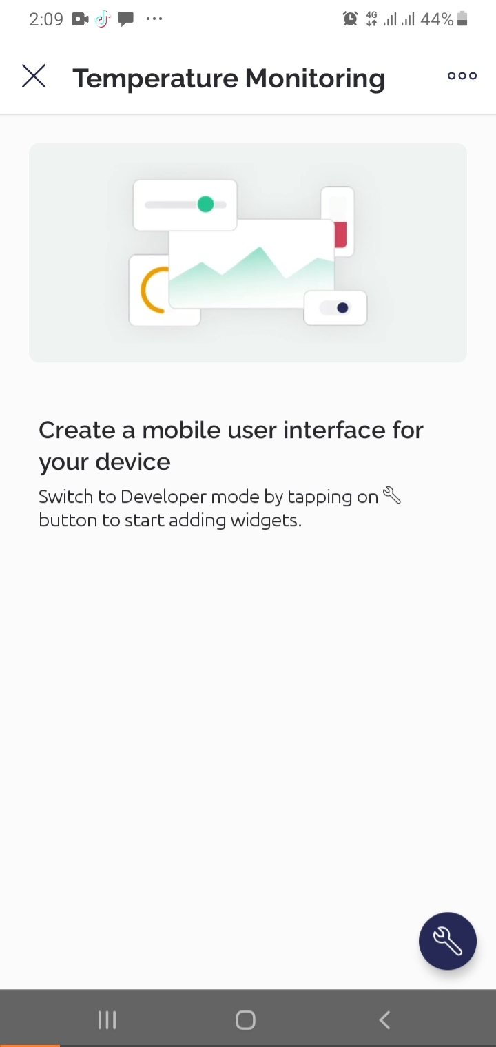
Tap the settings icon to enter Developer Mode:
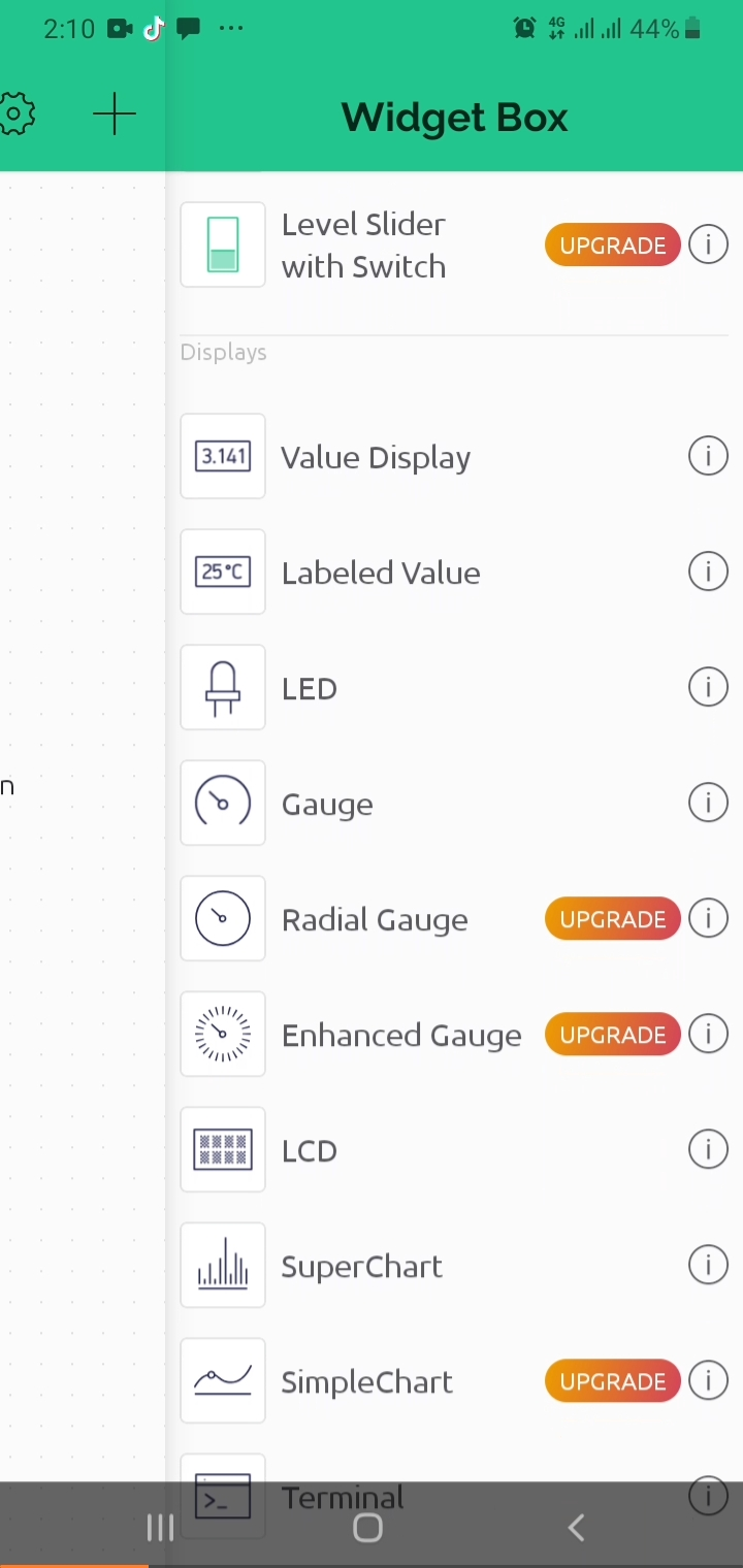
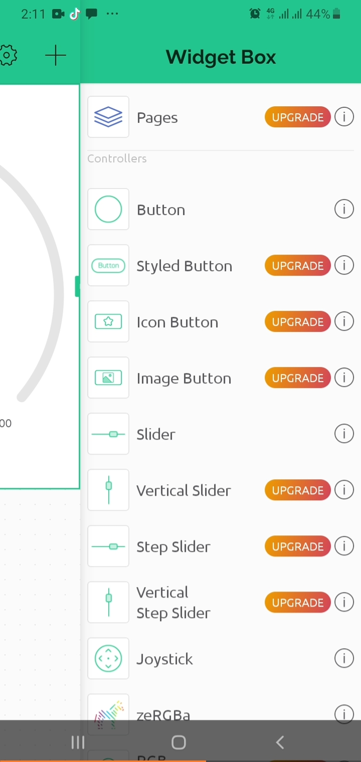
Tap the + button and add a Gauge widget:
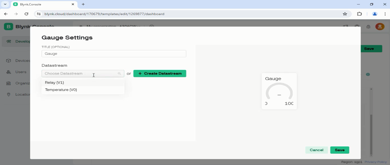
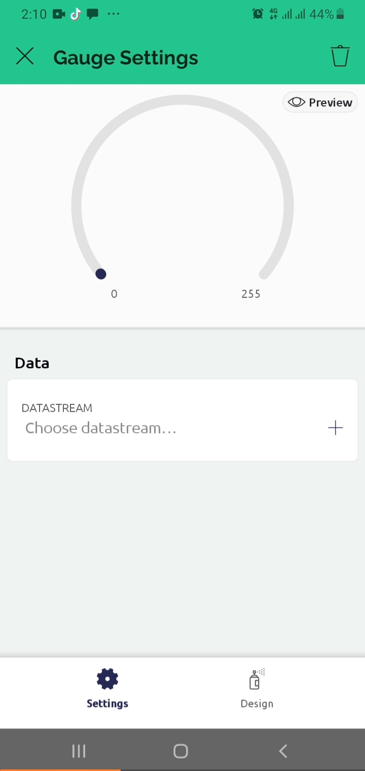
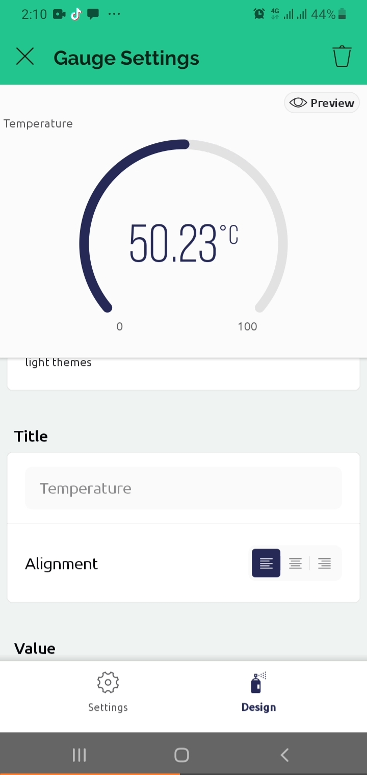
Tap the Gauge to open its settings:
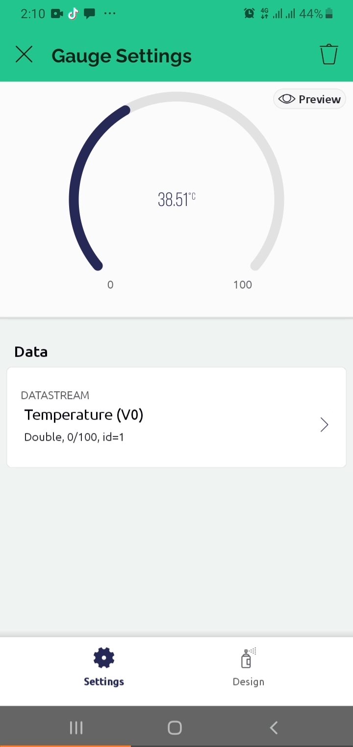
Link Datastream V0 to the Gauge:
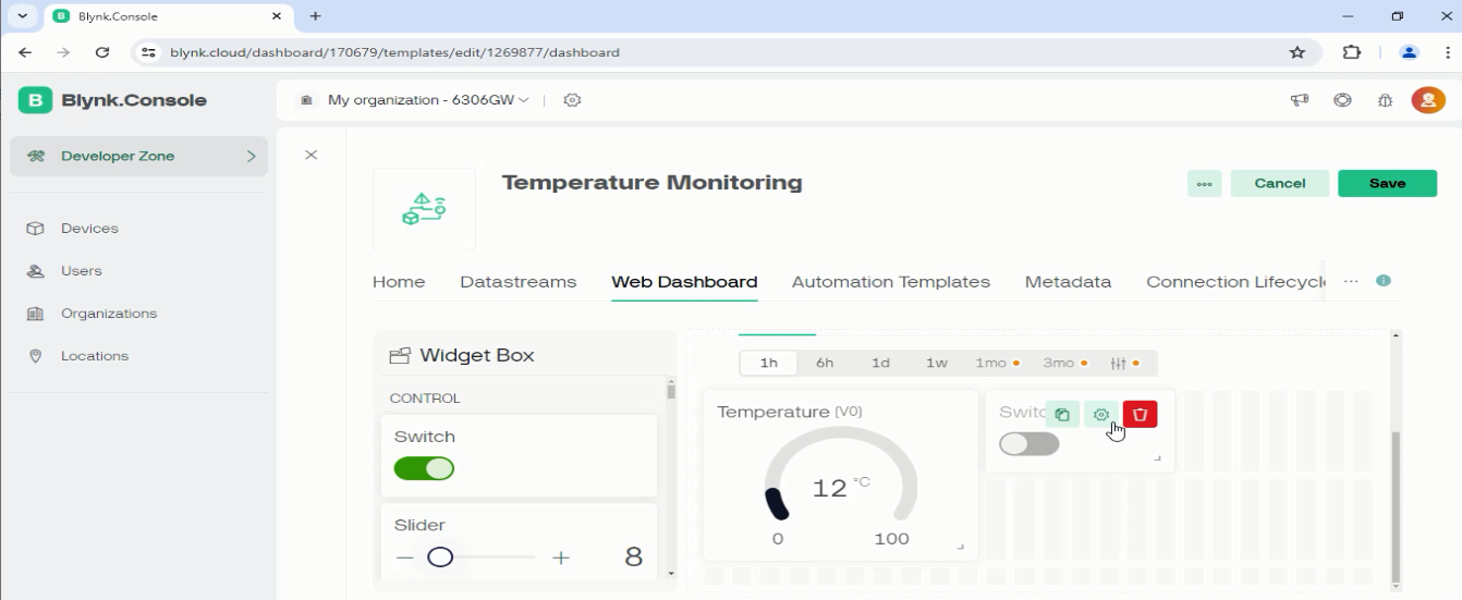
Adjust the text size and add a title to the Gauge:
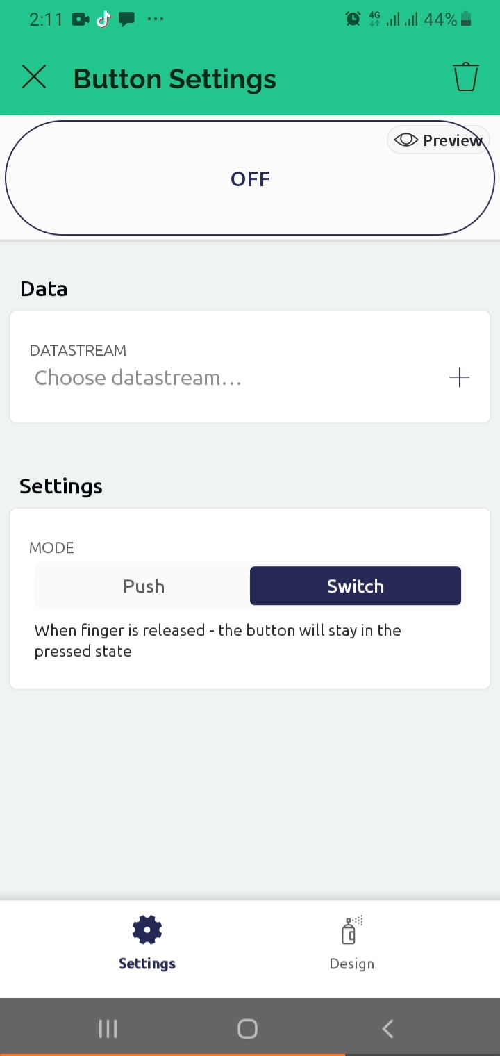
Tap + again to add a Button widget for relay control:
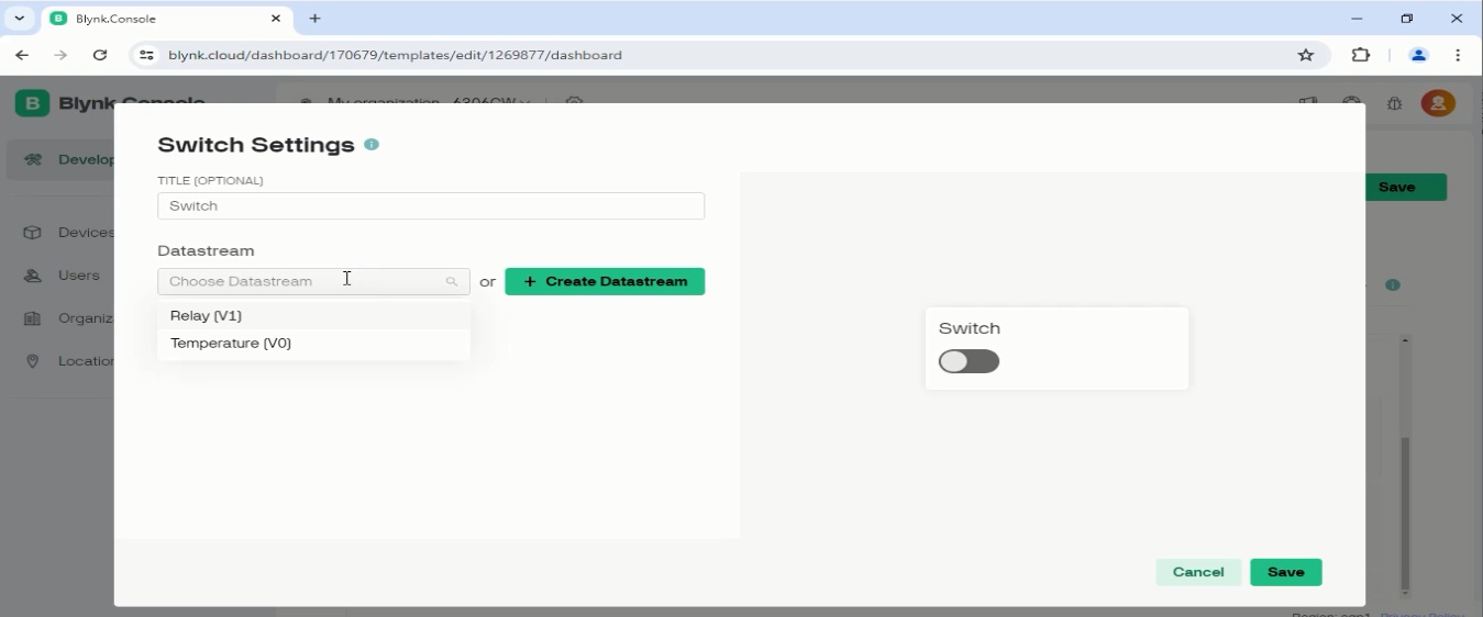
Tap the button widget and configure its mode as Switch, then link it to Datastream V1:
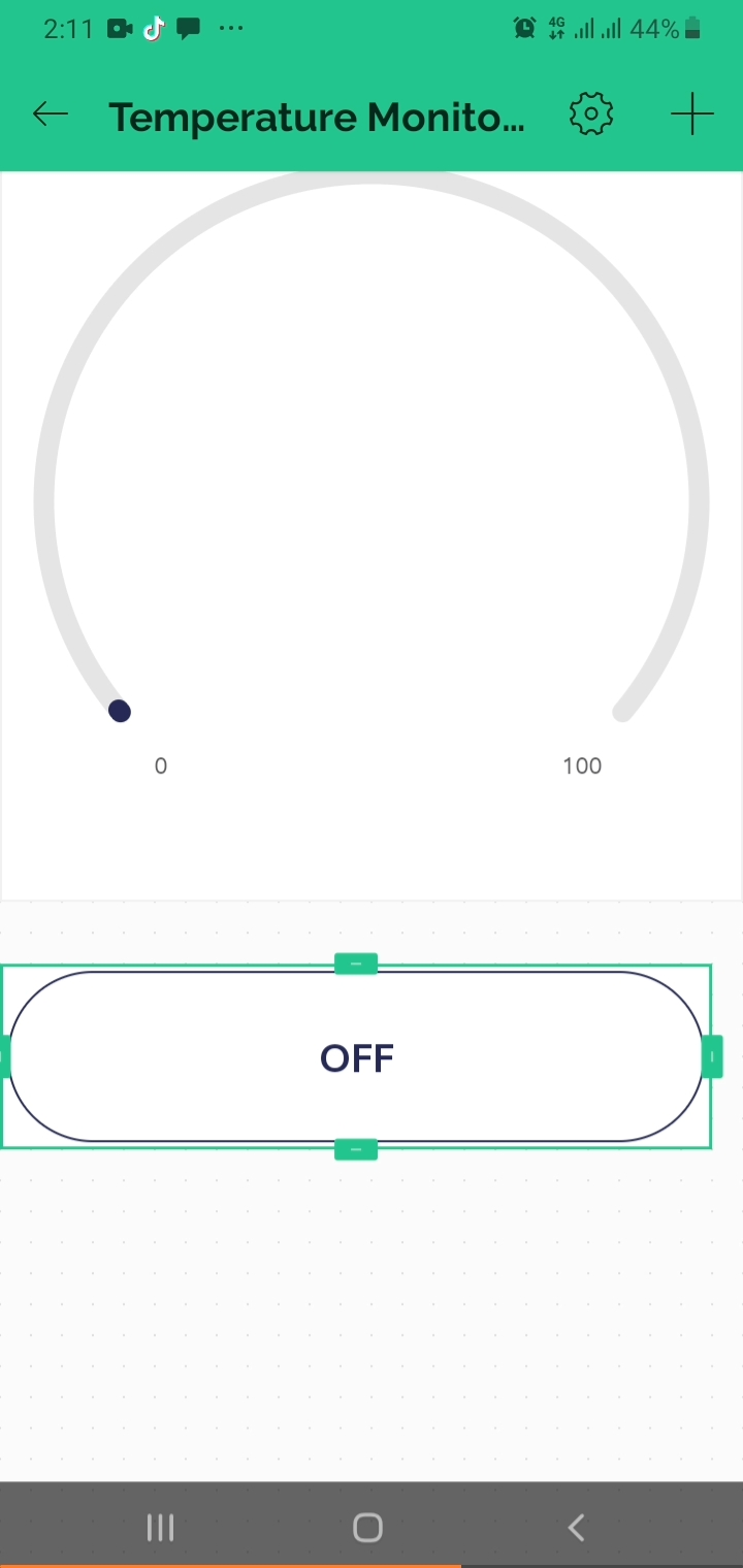
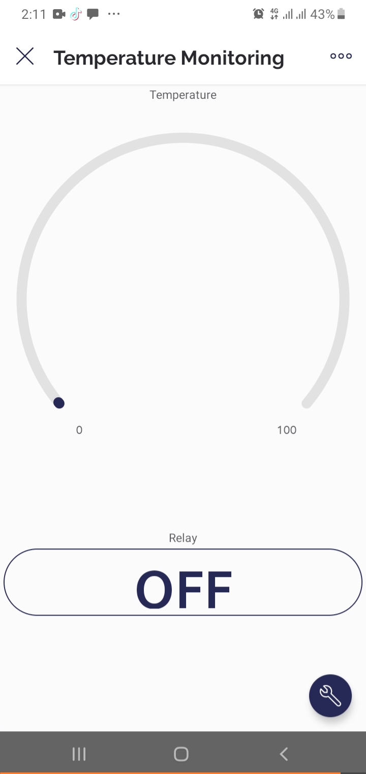
The mobile dashboard is now ready. Temperature data will appear on the Gauge and the relay can be toggled via the Switch in real time:
These ten projects step through the core capabilities of the ESP32 in a structured progression: digital output, digital input, analog sensing, display peripherals, sensor integration, and finally cloud-connected remote monitoring and control. Each project builds directly transferable skills applicable to more complex embedded systems and production IoT deployments.
When you are ready to take your ESP32 design from breadboard to a finished PCB, NextPCB offers fast-turnaround PCB fabrication and full assembly services to support every stage from prototype to production.

Still, need help? Contact Us: support@nextpcb.com
Need a PCB or PCBA quote? Quote now

