NextPCB Capabilities
 PCB Assembly
 Layer Buildup
 SMD-Stencils
 PCB Design-Aid & Layout
 Mechanics
 Quality
 Drills & Throughplating
 Factory & Certificate





USB is the most common way modern hardware moves both data and power over a single cable — which is exactly why a generic retail USB cable often doesn't work inside a real product. Wrong length, wrong connector orientation, not enough current capacity, or no strain relief for an enclosure cutout: any of these can turn a "just use a standard cable" decision into a field issue. Here's what to actually specify.
These are 3 of the 11 cable and wire harness types NextPCB manufactures — see the full comparison guide for external connector types like USB, D-Sub, and RF coaxial.
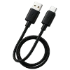
Why Custom USB Assemblies Exist
Off-the-shelf USB cables are built for general consumer use — a fixed length, a fixed connector pair, and wire gauge sized for typical charging loads. Custom assemblies solve problems standard cables can't:
- Exact length to match internal routing or external cable-management requirements
- Connector orientation and housing that fits a specific enclosure cutout or panel mount
- Wire gauge matched to actual current draw, not a generic assumption
- Shielding tuned to the product's EMI environment, especially relevant near RF or motor components
Key Specification Points
Connector type. USB-C, USB-A, USB-B, and Micro-USB all serve different roles — USB-C for modern power delivery and data, USB-A/B for legacy peripheral connections, Micro-USB still common in cost-sensitive embedded designs. Confirm which end needs to mate with which device.
Data vs. power vs. both. A pure charging cable can use simpler wiring than one that also carries high-speed data — mixing the two roles into a single cable means both jobs need to be specified correctly, not just the higher-priority one.
Wire gauge for current draw. USB Power Delivery can carry meaningfully more current than a basic charging port. If your device pulls close to the connector's rated current, undersized wire gauge shows up as voltage drop and heat, not just a slower charge.
Shielding. USB data lines are differential pairs sensitive to noise. In products with motors, switching power supplies, or RF modules nearby, shielding (and sometimes twisted-pair construction) prevents data errors that are hard to reproduce in a clean lab environment.
Common Mistakes to Avoid
Assuming a generic cable's gauge covers your load. Retail cables are sized for typical consumer charging, not necessarily your product's actual current draw — confirm gauge against real numbers, not assumptions.
No strain relief at the enclosure exit point. A cable that flexes at the same point every time it's plugged in or moved will eventually fatigue and fail at that point without a molded or added strain relief.
Ignoring connector orientation until the enclosure is already tooled. Right-angle vs. straight connectors, and which side the cable exits from, are much cheaper to fix on paper than after enclosure tooling is cut.
Overlooking the "both ends" requirement. It's easy to spec the device-side connector carefully and treat the host-side connector as an afterthought — both ends need to actually match what they'll plug into.
Where Custom USB Assemblies Are Used
- Consumer electronics with charging or data sync requirements
- Embedded systems with USB-based power delivery
- Peripheral devices (readers, sensors, controllers) needing a specific cable length or connector angle
- Products requiring higher-current USB-C Power Delivery wiring
If your product's power needs go beyond what a USB connector is rated for, see our power cable assembly guide for wire gauge and connector selection at higher current.
Frequently Asked Questions
Why does a USB-C cable need an "e-marker" chip for higher power?
USB-C cables rated above 3A (60W at 20V) are required to contain an e-marker chip that reports the cable's current capacity, voltage rating, and data speed to the charger during negotiation. Without an e-marker, a charger defaults to a lower current ceiling regardless of the cable's actual wire gauge. This matters for custom assemblies because the e-marker's programmed rating and the physical wire gauge both need to genuinely support the current your product will draw — one without the other creates a safety gap.
What wire gauge do I need for USB-C Power Delivery at higher wattages?
It depends on the power level: standard USB-C cables typically support around 60W (3A at 20V), while 100W support requires 5A-rated conductors along with an e-marker chip, and the newer 240W Extended Power Range spec requires cable specifically rated for 48V/5A. Conductor gauge should be selected to match the actual current the design will draw, with margin, rather than assumed from a "USB-C" label alone.
Can the same USB cable handle both high-speed data and high-wattage charging over a long length?
Not always. Delivering higher wattage over longer cable runs generally requires higher voltage to avoid excessive resistive loss, which leaves less design margin for the high-speed data lines in the same cable. A cable optimized for long-distance charging may not simultaneously support the fastest data-transfer specification, so it's worth confirming both requirements against the specific cable build rather than assuming a single cable does both equally well at any length.
Does USB connector type limit how much current I can draw?
Yes — different USB connector types and cable ratings are built for different maximum currents (commonly 3A or 5A for USB-C), and no standard USB-C cable or device is expected to exceed 5A. If your product needs more current than USB can reliably deliver, a dedicated power connector is usually the better choice — see our power cable assembly guide.
Why did my custom USB cable overheat even though it was "rated" for the current?
This is a known real-world issue: some cables are sold or labeled with a current rating (often via an e-marker chip) that doesn't match the actual conductor gauge inside them, since nothing physically enforces that the two match. Working with a manufacturer that verifies gauge against the rated current — rather than relying on a labeled spec alone — avoids this mismatch.
Get a Custom USB Cable Assembly Quote
NextPCB builds USB cable assemblies to your exact connector type, length, wire gauge, and shielding requirements — from a 1-piece prototype to full production, with the same IPC/WHMA-A-620 workmanship standard across every order.
Know your connector type, length, and current draw? Configure your USB cable assembly →
Not sure the wire gauge will actually support your product's power draw? This is the detail that causes overheating issues after the fact — tell our team your voltage and current requirements and they'll confirm the right gauge before you quote.
Building the board this cable connects to? USB cable termination can be handled in the same production run as your turnkey PCBA order. Visit the Cable Assembly Services page for full capabilities, or browse the NextPCB homepage for our full range of services.