NextPCB Capabilities
 PCB Assembly
 Layer Buildup
 SMD-Stencils
 PCB Design-Aid & Layout
 Mechanics
 Quality
 Drills & Throughplating
 Factory & Certificate





Voice assistants, LED matrices, and audio visualizers all boil down to the same underlying question: how do you take a signal — sound, time, a sensor reading — and turn it into something a person can see or hear in real time? The five projects below approach that question from very different angles, from a full conversational AI running on a $5 microcontroller to a business-card-sized frequency spectrum analyzer. Each one links back to its original build log with schematics, firmware, and assembly notes.
- In This Article
- 1. Pocket-Size ESP32 AI Voice Assistant (Xiaozhi)
- 2. Electro Retro — A Credit-Card-Sized ESP32-S3 Gaming Handheld
- 3. Audio Visualizer Business Card
- 4. Pi Synth — A Multiplexed Synthesizer on a Raspberry Pi Pico
- 5. DIY 8×32 LED Matrix Smart Clock (Awtrix 3.0)
1. Pocket-Size ESP32 AI Voice Assistant (Xiaozhi)
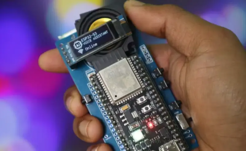
Commercial smart speakers hide a fair amount of complexity behind a single wake word, and this project is a good way to see what that complexity actually looks like. Instead of running a large language model directly on the microcontroller (an ESP32-S3 has nowhere near the memory or compute for that), the design uses a hybrid edge-plus-cloud architecture: the board handles audio capture and playback locally, then streams the audio to the open-source Xiaozhi backend, which runs the actual speech recognition and language model and sends a spoken response back over Wi-Fi.
The hardware side is intentionally minimal. An INMP441 digital I2S microphone captures audio without the noise floor of an analog mic, and a MAX98357A I2S amplifier drives the speaker directly, so the circuit never needs a separate DAC. A small OLED screen displays status and responses, and the whole thing fits inside a 3D-printed sliding-cover enclosure sized around a coin-cell-thin PCB.
What makes this build worth studying isn't the AI model — it's the edge/cloud split. Anyone prototyping a voice-controlled IoT device runs into the same tradeoff: keep everything local and accept a smaller vocabulary and slower response, or offload to the cloud and accept a network dependency. This project's answer — do only signal capture and playback on-device, let the cloud handle language — is a pattern worth borrowing even outside voice-assistant projects.
Components:
- ESP32-S3
- INMP441 I2S MEMS Microphone
- MAX98357A I2S Amplifier
- 0.91″/0.96″ OLED Display
- Xiaozhi Open-Source Firmware
- 3D-Printed Enclosure
Full build log and firmware repository on Hackster.io, source files on GitHub, and a companion walkthrough on Instructables.
2. Electro Retro — A Credit-Card-Sized ESP32-S3 Gaming Handheld

Most DIY Game Boy–style handhelds top out at wallet size. Electro Retro goes further, fitting a color display, Wi-Fi, microSD storage, USB-C charging, and a built-in 1W speaker onto a board roughly the size of a credit card, while still emulating Game Boy, Game Boy Color, NES, and Sega Master System titles.
The build process is a useful reference for anyone designing a compact battery-powered handheld: the creator started with a schematic covering the ESP32-S3, display, battery charging circuit, audio amplifier, and button matrix, then hand-routed the PCB with careful component placement to keep the footprint small before sending it out for fabrication. The full schematic and PCB layout are published openly, which is unusually generous for a project this polished.
The interesting engineering tradeoff here is thermal and power density — cramming a Wi-Fi radio, a battery charge controller, and audio amplification into a credit-card footprint means every component placement decision affects both routing and heat dissipation. It is a good case study in what compact handheld PCB layout actually requires once you move past a breadboard prototype.
Components:
- ESP32-S3
- Color TFT Display
- microSD Card Slot
- USB-C Charging Circuit
- 1W Speaker
- Custom 2-Layer PCB (schematic on OSHWLab)
Full build log on Hackster.io, schematic and PCB files on OSHWLab, and the companion guide on Instructables.
3. Audio Visualizer Business Card
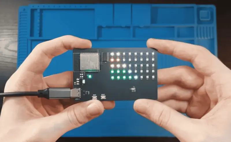
PCB business cards are a well-worn maker tradition, but most either do nothing beyond looking sharp or perform one simple trick, like flashing an LED. This one raises the bar: a functioning audio visualizer, frequency spectrum analyzer, and customizable display, all built into a card-sized board thin enough to carry in a wallet.
Projects like this typically work by sampling an audio input, running a lightweight FFT (Fast Fourier Transform) on a microcontroller to split the signal into frequency bands, and mapping the amplitude of each band to a column or row of LEDs — the same basic principle behind the spectrum displays on a home stereo, just squeezed onto a card 0.6–0.8mm thick. Getting a functional spectrum analyzer, a display driver, and a battery or USB power path onto something that thin is as much a mechanical design challenge as an electrical one.
For anyone designing their own PCB business card, this project is a good reminder that “does something” and “does something worth showing off” are two different bars — and that audio-reactive visuals tend to clear the second one more reliably than a blinking LED.
Components:
- Card-Format PCB (~0.6–0.8mm)
- Onboard Microphone or Line-In Input
- LED Matrix Display
- FFT-Based Spectrum Analysis Firmware
- Coin-Cell or USB Power
Note: this project's public write-up does not disclose a specific MCU or LED driver part number, so the list above reflects the functional blocks described rather than exact component references.
See the full project write-up on Hackaday.io.
4. Pi Synth — A Multiplexed Synthesizer on a Raspberry Pi Pico
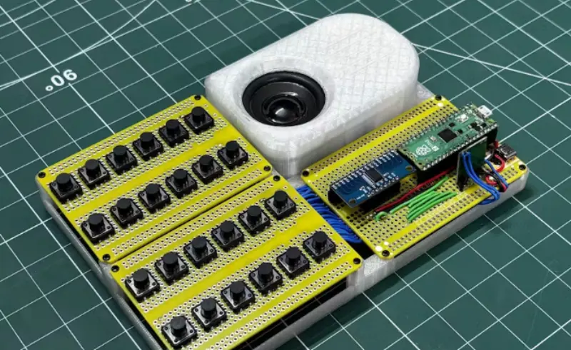
A Raspberry Pi Pico only exposes 26 usable GPIO pins, which is a problem the moment you want a synthesizer with more than a handful of physical controls — keys, knobs, sliders, mode switches. Pi Synth solves this with a CD74HC4067 16-channel analog multiplexer, letting a single ADC pin on the Pico read up to 16 potentiometers or buttons in sequence instead of needing a dedicated pin for each one.
This multiplexing trick is worth understanding even if you never build a synthesizer: it is the standard answer any time a microcontroller project needs more analog inputs than it has physical pins, and it shows up constantly in DIY audio gear, custom MIDI controllers, and sensor arrays alike. Pi Synth is a clean, well-documented reference implementation of the pattern.
Components:
- Raspberry Pi Pico (RP2040)
- CD74HC4067 16-Channel Analog Multiplexer
- Potentiometer/Button Control Surface
- Custom PCB
Full build log on Hackster.io, with additional coverage on Instructables and Hackaday.io.
5. DIY 8×32 LED Matrix Smart Clock (Awtrix 3.0)
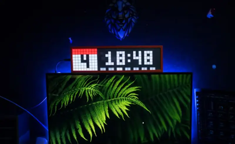
Awtrix 3.0 is open-source firmware that turns an ESP32 and an 8×32 addressable LED matrix into a pixel-art smart display — time, weather, notifications, and custom apps, all rendered a few pixels at a time. This build pairs the firmware with a BMP280 pressure and temperature sensor and a 3D-printed case with physical buttons for cycling between display modes, turning a software project into a genuinely useful desk clock.
The appeal of the Awtrix ecosystem is that most of the hard problems — matrix driving, app switching, MQTT integration for smart-home notifications — are already solved in the firmware, which means the build effort goes into fabrication and enclosure design rather than reinventing display logic from scratch. That makes it one of the more approachable entries on this list for anyone newer to custom PCB assembly.
Components:
- ESP32
- 8×32 Addressable LED Matrix (WS2812-type)
- BMP280 Temperature/Pressure Sensor
- Awtrix 3.0 Open-Source Firmware
- 3D-Printed Enclosure with Physical Buttons
Full build log on Hackster.io, with a companion guide on Instructables.
Quick Reference: Core Hardware by Project
| Project | Main MCU | Standout Component | Output |
| Xiaozhi AI Voice Assistant | ESP32-S3 | INMP441 I2S microphone | Speaker + OLED |
| Electro Retro | ESP32-S3 | Custom credit-card PCB | Color TFT display |
| Audio Visualizer Business Card | Not disclosed | FFT spectrum analysis | LED matrix |
| Pi Synth | RP2040 (Pico) | CD74HC4067 multiplexer | Audio out |
| Awtrix Smart Clock | ESP32 | BMP280 sensor | 8×32 LED matrix |
Frequently Asked Questions
What chip do most DIY ESP32 voice assistant projects use?
Most current builds use the ESP32-S3 rather than the original ESP32, since the S3 variant has more RAM and better support for I2S audio peripherals, which makes wiring a digital microphone and amplifier straightforward without extra DAC hardware.
Can an ESP32 run AI voice recognition entirely on-device?
Not for general conversation. Most ESP32-based voice assistants, including the Xiaozhi-based build above, use a hybrid architecture: the board handles audio capture and playback locally, while speech recognition and language processing run in the cloud. Fully on-device voice AI on a microcontroller is generally limited to small, fixed vocabularies (wake words or single-digit commands), not open-ended conversation.
How do you add more analog inputs to a Raspberry Pi Pico than it has pins?
The standard approach is an analog multiplexer chip, such as the CD74HC4067 used in the Pi Synth project above. It lets a single ADC-capable pin read from up to 16 separate analog inputs in sequence, which is far more pin-efficient than wiring each potentiometer or sensor to its own GPIO.
What firmware is used for DIY pixel-matrix smart clocks?
Awtrix 3.0 is the most widely used open-source firmware for ESP32-based LED matrix clocks. It handles matrix driving, app switching, and smart-home notification integration out of the box, so builders can focus on hardware fabrication rather than display logic.
Building Something Similar?
If you are prototyping a project along these lines, NextPCB's free online Gerber Viewer and DFM tool is worth running your design through before ordering, and the NextPCB Accelerator program covers PCBA costs for qualifying open-source hardware projects.