Key Takeaways for Engineers
- Q: What is the fundamental performance gap between Aluminum and Copper PCBs?
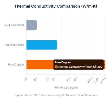
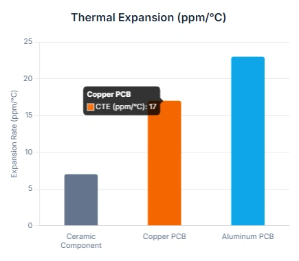
- A: Copper boasts a thermal conductivity of approximately 400 W/m·K, which is nearly double that of high-grade Aluminum alloys (138–238 W/m·K). Furthermore, Copper’s Coefficient of Thermal Expansion (CTE) is much closer to that of LED components and solder, significantly reducing mechanical stress during thermal cycling.
- Q: When is it mandatory to switch to Copper-Core PCBs?
- A: In typical high-power LED designs, engineers often prefer copper-core substrates when power density exceeds approximately 2 W/cm². DTP allows the thermal pad of a component to sit directly on the metal base, eliminating the dielectric thermal bottleneck.
- Q: Is Aluminum still the most cost-effective for 2026?
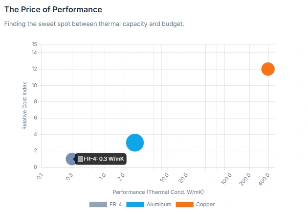
- A: Yes. For general LED lighting and mid-range power supplies (under 100W), Aluminum remains the most cost-effective solution, offering a weight reduction of nearly 66% compared to Copper.
- Q: How does the PCB choice affect LED longevity?
- A: Efficient heat dissipation directly lowers junction temperatures. Reducing operating temperatures by just 10°C can effectively double a component's lifespan. In certain high-power configurations, copper DTP boards have been reported to operate up to 30–35°C cooler than standard aluminum MCPCBs, depending on stackup and airflow.
As the electronics industry pushes toward higher power densities and extreme miniaturization, traditional FR-4 glass-epoxy laminates are increasingly becoming the weak link. With a thermal conductivity typically below 1.0 W/m·K, FR-4 cannot keep pace with the heat generated by modern AI servers, EV inverters, and high-intensity LED arrays.
To bridge this gap, Metal Core PCBs (MCPCBs)—also known as Insulated Metal Substrates (IMS)—have become the industry standard. This report provides a technical comparison between Aluminum and Copper substrates to help engineers make data-driven decisions for their next high-performance project.
- Table of Contents
- Key Takeaways for Engineers
- Introduction
- 1. The Physics of Thermal Management in PCBs
- 2. Aluminum PCBs: The Efficient Industry Workhorse
- 3. Copper PCBs: For Extreme Power and High-Reliability Applications
- 4. Reliability and Thermal Stress Analysis
- 5. Manufacturing Challenges and Tolerances
- 6. LED Specific Optimizations
- 7. Decision Matrix: Choosing Your Core
- 8. Example Manufacturing Capabilities (Typical for Advanced MCPCB Suppliers)
- 9. 2025-2026 Technical Outlook: From MCPCB to Integrated Cooling
- 10. Conclusion
- 11. Metal Core PCB FAQ: Copper vs. Aluminum
1. The Physics of Thermal Management in PCBs
Effective thermal design aims to reduce the total thermal resistance from the semiconductor junction to the ambient environment. In a typical MCPCB, heat follows two primary paths:
1.1 Dielectric Barriers vs. Vertical Conduction
In a standard metal core board, heat must pass through a dielectric insulation layer before reaching the metal base. While the metal itself is highly conductive, this dielectric layer often acts as a bottleneck. Modern high-performance dielectrics offer thermal conductivities between 1.0 and 10 W/m·K, a significant improvement over standard FR-4, yet still orders of magnitude lower than the metal base.
1.2 Lateral Spreading
Once heat enters the metal core, it spreads laterally across the board. The thickness of the core (ranging from 0.6mm to 3.2mm) and the material's intrinsic conductivity determine how effectively "hotspots" are eliminated. Copper's superior spreading capability ensures a more uniform temperature distribution across the entire assembly.
| Physical Property |
Unit |
Aluminum (5052 Aluminum Alloy) |
Copper (C1100) |
| Thermal Conductivity (Base) |
W/m·K |
138 – 238 |
390 – 401 |
| Density |
g/cm3 |
2.70 |
8.96 |
| CTE (Thermal Expansion) |
ppm/°C |
23 – 25 |
16 – 17 |
| Elastic Modulus |
GPa |
~70 |
~121 |
| Electrical Conductivity |
MS/m |
37.8 |
58.0 |
2. Aluminum PCBs: The Efficient Industry Workhorse
Aluminum MCPCBs dominate roughly 80% to 90% of the metal core market due to their excellent balance of performance and affordability.
Strategic Alloy Selection
- 5052 Aluminum Alloy: The most popular choice for LED applications. It provides high thermal conductivity (≥ 2.0 W/m·K for the laminate) and sufficient mechanical strength for most consumer and industrial lighting.
- 6063 Aluminum Alloy: Highly malleable and often used when the PCB also serves as a structural chassis or an extruded heat sink housing.
- 1060/1100 Series: Higher purity alloys with better thermal performance than the 5000 series, but with lower hardness, making them prone to deformation during machining.
Market Positioning and Weight Advantages
Aluminum is approximately three times lighter than copper. This makes it the only viable option for weight-sensitive applications such as drones, handheld medical devices, and portable consumer electronics. In terms of cost, single-sided Aluminum boards generally run 30% to 50% cheaper than their Copper counterparts.
3. Copper PCBs: For Extreme Power and High-Reliability Applications
When power density reaches extreme levels—common in automotive headlights and laser modules—Aluminum reaches its saturation point. In these scenarios, Copper-Core PCBs are the more reliable choice.
Thermoelectric Separation and Pedestal Technology
Copper's greatest advantage is its compatibility with "Direct Thermal Path" (DTP) technology. In DTP designs, the dielectric layer is selectively removed, allowing the component’s thermal pad to be soldered directly to the copper base.
This creates a "thermoelectric separation" where the electrical signals follow the circuit traces, but the heat takes a "shortcut" directly into the copper. This method elevates the effective thermal conductivity to nearly 400 W/m·K, whereas standard IMS boards are limited by the dielectric to roughly 1-10 W/m·K. While aluminum can attempt a pedestal process, its chemical properties and physical softness make it far inferior to copper for high-quality bonding and oxidation resistance.
Heavy Copper and EMI Shielding
Copper-Core boards are ideal for high-current applications. They can support integrated thick-copper layers (thick-copper pcb technology) up to 10 oz, reducing resistive losses. Furthermore, the solid copper base acts as a natural EMI shield, protecting sensitive signal layers in complex industrial or medical equipment.
4. Reliability and Thermal Stress Analysis
Mechanical failure in PCBs often stems from a mismatch in the Coefficient of Thermal Expansion (CTE).
- CTE Matching: Ceramic LED packages have a low CTE (approx. 6–7 ppm/°C). Copper (16–17 ppm/°C) is a much better match than Aluminum (23–25 ppm/°C). This closer match reduces the shear stress on solder joints during rapid temperature fluctuations.
- Vibration Resistance: Copper has an elastic modulus 70% higher than Aluminum, providing superior rigidity. This makes Copper-Core boards highly reliable in high-vibration environments like medical imaging systems (MRI/CT), robotics, or automotive electronics.
5. Manufacturing Challenges and Tolerances
Processing metal-core boards requires specialized equipment compared to standard FR-4.
- Machining: Aluminum is soft and easy to route or V-score with standard tools. Copper, however, is "gummy" and harder, which causes rapid wear on drill bits and requires slower feed rates to prevent burrs.
- Etching: Thick copper layers require longer etching times, which increases the risk of "undercutting". Precision compensation is required during the design phase to maintain trace integrity. Aluminum PCBs are typically used for single-sided or double-sided metal core structures but can support more complex stacks depending on fabrication technology.
| Process Item |
Aluminum Difficulty |
Copper Difficulty |
Note |
| CNC Routing |
Low |
Medium |
High tool wear for copper |
| V-Scoring |
Low |
Medium |
Copper requires diamond blades |
| Drilling |
Low |
High |
Copper prone to burrs; needs annealing |
| PTH (Plated Through Hole) |
Very High |
Low |
Copper supports multilayer interconnects |
6. LED Specific Optimizations
For LED designs, optical performance is just as critical as thermal management. Temperature increases lead to reduced light output, color shifts, and wavelength changes.
- High-Reflectivity Solder Mask: Using a specialized white solder mask can reflect 85–90% of incident light. High-reflectivity, UV-stabilized white solder masks are commonly used in high-power LED applications to maintain optical performance after multiple reflow cycles.
- Direct Thermal Path (DTP) & Pedestal: In extreme power density fields like automotive headlights or medical surgical lights, DTP copper boards are the standard. By etching or plating copper pedestals that pass through the dielectric, a zero-resistance thermal path is achieved.
7. Decision Matrix: Choosing Your Core
Use Aluminum When:
- Total power load is under 2 Watts/cm2.
- Cost optimization is a primary driver for mass production (30-50% cheaper).
- Weight is critical (portable electronics, drones, handheld medical devices).
- The application is general lighting (bulbs, strips, office panels).
Use Copper When:
- Power density is extreme or individual LEDs exceed 5-10W.
- High reliability is required for mission-critical systems (Headlights, Industrial Lasers).
- Environment involves extreme vibration or rapid thermal cycles (-40 to 125°C).
- You need multilayer complexity with Plated Through Holes (PTH).
8. Example Manufacturing Capabilities (Typical for Advanced MCPCB Suppliers)
| Specification |
Capability (NextPCB) |
Note |
| Layer Count |
1 – 32 Layers |
Supports complex multilayer structures |
| Max Dimensions |
1200 x 540 mm |
Ideal for large LED arrays |
| Copper Weight |
0.5 oz to 10 oz |
Heavy copper support for high current |
| Aluminum Thickness |
0.4 mm to 3.0 mm |
Includes 1.0/1.6/2.0mm standards |
| CNC Routing Tolerance |
±0.15 mm |
Ensures precise outline dimensions |
| V-CUT Residue |
0.25 mm to 0.4 mm |
Balance between strength and depaneling |
| Dielectric Conductivity |
1.0 to 10 W/m·K |
Multiple high-performance options |
9. 2025-2026 Technical Outlook: From MCPCB to Integrated Cooling
- Advanced Ceramic Fillers: Dielectrics filled with Aluminum Nitride (AlN) will double the thermal conductivity of standard MCPCBs, closing the gap between aluminum and copper for mid-range apps.
- COB and CSP Packaging: Chip Scale Packages require extreme flatness and fine line/space (2/2 mil), driving the use of high-precision laser processing on copper substrates.
- Green Manufacturing: Many manufacturers (including NextPCB) are adopting lead-free/halogen-free high thermal stability resins in their designs to comply with environmental trends and ISO 14001.
10. Conclusion
The choice between Aluminum and Copper is not a matter of "better" or "worse," but of matching the right material to the specific budget and performance requirements. Aluminum remains the king of value for general lighting, while Copper provides unmatched stability for high-stakes automotive and medical applications. By leveraging NextPCB’s heavy copper and thermoelectric separation technologies, engineers can ensure their products thrive even in the harshest thermal environments.
11. Metal Core PCB FAQ: Copper vs. Aluminum
Q1: Why do my metal-core boards sometimes have weak or "cold" solder joints?
Metal-core boards act as massive heat sinks. During assembly, they pull heat away from the pads so quickly that the solder may not melt properly.
Solution: We recommend a pre-heating stage (100°C–150°C) before soldering. NextPCB’s SMT lines use customized reflow profiles for every metal-core project to ensure good wetting.
Q2: Copper is expensive—are there middle-ground solutions?
If you need better performance than standard Aluminum but can't justify Copper, consider:
- High-Conductivity Aluminum: Utilizing 3.0 W/m·K dielectrics instead of standard 1.0.
- Copper Coin Technology: Embedding a small copper "coin" in a standard FR-4 board.
- Heavy Copper FR-4: Increasing copper thickness (2oz or 3oz) for lateral spreading.
Q3: What are the design requirements for the stackup?
Metal-core boards are different from FR-4. When submitting your Gerber files:
- Clearly define the dielectric thickness (typically 0.05mm – 0.15mm).
- Include a Layer Stackup diagram specifying the metal core material (AL or CU) and the surface finish (OSP or HASL).
Q4: Does NextPCB support complex machining for these boards?
Yes. NextPCB supports advanced capabilities including blind and buried vias, as well as z-axis milling for controlled-depth cavities, specifically designed for high-power LED and automotive applications.
Expert Consultation
Unsure which material fits your power budget? NextPCB offers professional engineering reviews.
- Get a Quote: Visit NextPCB Quote Page for instant pricing.
- Technical Support: Our engineers will review your Stackup design for free to ensure manufacturing feasibility.
About the Author
Arya Li, Project Manager at NextPCB.com
With extensive experience in manufacturing and international client management, Arya has guided factory visits for over 200 overseas clients, providing bilingual (English & Chinese) presentations on production processes, quality control systems, and advanced manufacturing capabilities. Her deep understanding of both the factory side and client requirements allows her to deliver professional, reliable PCB solutions efficiently. Detail-oriented and service-driven, Arya is committed to being a trusted partner for clients and showcasing the strength and expertise of the factory in the global PCB and PCBA market.

 Surface


 NextPCB Capabilities
 PCB Assembly
 Layer Buildup
 SMD-Stencils
 PCB Design-Aid & Layout
 Mechanics
 Quality
 Drills & Throughplating
 Factory & Certificate
 PCB Assembly Factory Show
Certificate
PCB Assembly Factory Show
Certificate


