
 Surface


Lolly Zheng- Sales Account Manager at NextPCB.com

 NextPCB Capabilities
Printed Circuit Boards
NextPCB Capabilities
Printed Circuit Boards
 PCB Assembly
 Layer Buildup
 SMD-Stencils
 PCB Design-Aid & Layout
 Mechanics
 Quality
 Drills & Throughplating
 Factory & Certificate
 PCB Assembly Factory Show
Certificate
PCB Assembly Factory Show
Certificate
Support Team
Feedback:
support@nextpcb.com


Introduction
In the rapidly evolving landscape of power electronics, thermal management is no longer an afterthought—it is a primary design constraint. As components like IGBTs, MOSFETs, and high-power LEDs shrink in size while handling higher current densities, traditional substrate materials often hit their thermal limits. For engineers tasked with ensuring reliability under extreme conditions, understanding the key advantages of ceramic PCBs is essential for successful high-power system design.
While FR-4 remains the industry standard for general-purpose electronics, it acts as a thermal insulator rather than a conductor. Even Metal Core PCBs (MCPCBs), designed for better heat dissipation, suffer from the thermal resistance of their dielectric layers. Ceramic Printed Circuit Boards (PCBs), utilizing materials like Alumina (Al2O3) or Aluminum Nitride (AlN), offer a robust solution by fundamentally changing how heat is transferred and how the board reacts to thermal stress.
This article explores the engineering principles behind ceramic substrates, focusing on thermal conductivity, mechanical reliability, and why they are the preferred choice for high power PCB substrate applications.
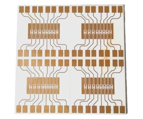
To understand the performance differences, we must first look at the base materials. Ceramic PCBs do not use an organic resin (epoxy) as the binder. Instead, the core is a solid ceramic slab.
Alumina is the most common ceramic substrate due to its balance of cost and performance.
For extreme high-power density designs, aluminum nitride PCB substrates are the premium choice.
Technical Note: Thermal Conductivity
Thermal conductivity (k) measures a material's ability to conduct heat. In PCB design, a higher k value means heat moves faster from the active component junction to the heatsink, lowering the junction temperature (Tj) and extending component life.
The primary reason engineers switch to ceramics is heat dissipation. However, the advantage isn't just about the raw thermal conductivity number; it is about the structural stack-up.
In a standard Metal Core PCB (MCPCB), the heat must travel through three layers:
Ceramic PCBs eliminate the insulating organic dielectric layer.
In technologies like Direct Bonded Copper (DBC), the copper foil is bonded directly to the ceramic surface at high temperatures. Since the ceramic itself acts as an electrical insulator and a thermal conductor, there is no intermediate barrier blocking heat flow. This structure drastically reduces the total thermal impedance (Rth) of the system. In practical designs, this can reduce junction-to-base thermal resistance by more than 30–50% compared to typical MCPCB stack-ups.
For a high power PCB substrate, this direct thermal path allows for significantly higher driving currents without raising the component junction temperature beyond safe operating areas (SOA).
Thermal issues often lead to mechanical failures before electrical ones. This is where the Coefficient of Thermal Expansion (CTE) becomes critical.
Technical Note: CTE (Coefficient of Thermal Expansion)
CTE measures how much a material expands when heated, usually expressed in parts per million per degree Celsius (ppm/°C).
Traditional FR-4 has a Z-axis CTE of roughly 50–70 ppm/°C (above Tg - glass transition temperature) and an X/Y CTE of 14–17 ppm/°C. Conversely, silicon dies and wide-bandgap semiconductors like Silicon Carbide (SiC) or Gallium Nitride (GaN) have a CTE of approximately 3–5 ppm/°C.
When a device heats up, the FR-4 board expands much faster than the chip soldered to it. This mismatch creates shear stress at the solder joints. Over thousands of power cycles (turning the device on and off), this stress causes solder fatigue, leading to cracks and open circuits.
Ceramic substrates have a CTE that closely matches semiconductor materials:
Because the expansion rates are synchronized, ceramic PCB advantages include significantly reduced stress on solder joints. This makes them indispensable for mission-critical applications in aerospace and automotive sectors where long-term reliability is non-negotiable.
High-power designs often involve high voltages. Ceramics offer excellent electrical isolation properties.
To aid in the selection process, the table below compares the three main substrate categories used in power electronics.
From an engineering selection perspective, the differences between these substrates can be summarized as follows:
| Feature | FR-4 (Standard) | Metal Core (MCPCB) | Ceramic PCB (Al2O3 / AlN) |
|---|---|---|---|
| Thermal Conductivity | ~0.3 W/m·K (Poor) | 1–4 W/m·K (Dielectric limit) | 24–170+ W/m·K (Excellent) |
| CTE Match to Silicon | Poor (High mismatch) | Moderate | Excellent (Close match) |
| Maximum Operating Temp | ~105°C – 130°C (continuous), up to 170°C (Tg) | ~105°C – 130°C (limited by dielectric) | > 300°C (substrate material) |
| Insulation Layer | FR-4 Core | Organic Dielectric | The Ceramic Substrate itself |
| Through-Holes | Plated Through Holes (PTH) | Difficult (Requires insulation) | Possible (Laser drilled/filled) |
| Cost | Low | Medium | High |
While FR-4 is cost-effective for logic circuits and an Aluminum PCB is suitable for standard LED lighting, the ceramic PCB for high power applications dominates where reliability and extreme heat flux are the defining parameters.
>> More Comparative Details: Ceramic PCB vs FR4 vs Metal-Core: Substrates for Thermal Management
When specifying ceramic PCBs, you will typically encounter two manufacturing methods:
In DBC, copper is bonded to the ceramic under high temperatures using a eutectic bond.
DPC utilizes vacuum sputtering and electroplating technology.
The unique properties of ceramic substrates make them the standard for several demanding industries:
Electric Vehicles (EVs) require inverters that convert DC battery power to AC for the motor. These traction inverters handle hundreds of amps. An aluminum nitride PCB is often used here to manage the immense heat generated by SiC MOSFETs, ensuring the vehicle operates reliably.
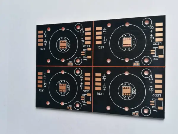
For UV curing lights or stadium lighting, the heat flux per square millimeter is intense. Alumina PCB substrates ensure the LED die remains cool, preventing color shift and extending the lumen maintenance life of the diode.
Solar inverters and wind turbine converters operate in harsh outdoor environments with massive temperature swings. The thermal cycling resilience of ceramics ensures these systems can operate for 20+ years without interconnect failure.
IGBT and Peltier modules rely almost exclusively on ceramic substrates (DBC) to isolate the electrical circuit from the heatsink while allowing maximum heat flow.
A: This is a matter of the "thermal ceiling." Generally, when your power components (such as MOSFETs or LEDs) exceed a heat flux of 10 W/cm², or when traditional FR-4 with thermal vias fails to keep junction temperatures ($T_j$) below safe limits (typically 125°C), ceramic substrates become necessary. Ceramic PCBs eliminate the "out-of-plane" thermal resistance inherent in organic laminates, providing a direct, highly conductive path that vias simply cannot match.
A: While ceramics have high hardness and compressive strength, they have low fracture toughness, meaning they are brittle. Cracks often occur during assembly due to uneven bolt torque, mechanical shock (like drops), or improper jigging. To mitigate this, we recommend avoiding high-stress mounting points near the edges of the board and using torque-limited tools or thermal interface materials (TIMs) to help buffer mechanical stress between the ceramic and the metal heatsink.
A: While common DBC and DPC processes are typically used for 1-layer or 2-layer designs, multilayer ceramic boards are possible through LTCC (Low Temperature Co-fired Ceramic) or HTCC (High Temperature Co-fired Ceramic) technologies. These allow for high-density integration (sometimes 40+ layers). However, due to higher costs and longer lead times, they are usually reserved for aerospace, medical, or highly integrated microwave power modules.
A: Alumina (Al₂O₃) has a $D_k$ of approximately 9.5, and Aluminum Nitride (AlN) is around 8.5—both significantly higher than FR-4 (~4.4). In RF designs, this requires smaller microstrip dimensions for impedance matching. However, the trade-off is excellent: ceramics offer an extremely low loss tangent (tan δ) and remain stable at high temperatures, making them superior to most organic high-frequency laminates for high-power RF amplifiers.
A: It comes down to copper thickness. DBC (Direct Bonded Copper) can easily achieve copper weights of 140µm to 350µm+ (4 oz to 10 oz+), which is essential for carrying hundreds of amps in IGBT modules or power inverters. In contrast, DPC (Direct Plated Copper) is a thin-film deposition process, typically limited to 10µm to 100µm. DPC is the better choice for high-precision, fine-line circuitry, but DBC remains the king of high-power distribution.
Choosing the right substrate is a pivotal decision in the hardware design process. While traditional FR-4 and Metal Core boards serve the mass market well, they cannot match the performance required for modern high-power density electronics.
The ceramic PCB advantages—specifically superior thermal conductivity (up to 170 W/m·K with AlN), excellent CTE matching with semiconductor dies, and high dielectric strength—make them the definitive choice for applications where failure is not an option. Whether you are designing a next-generation EV inverter or a high-intensity laser system, integrating ceramic substrates provides the thermal headroom and mechanical reliability necessary to push your design to its limits.
For engineers looking to transition from MCPCBs to ceramics, consulting with a specialized ceramic PCB manufacturer early in the design phase is crucial. Furthermore, ensuring your partner offers robust PCB assembly services is critical for handling these specialized boards.
At NextPCB, leveraging our extensive PCB manufacturing capabilities and early material consultation can help optimize the choice between Alumina and Aluminum Nitride based on specific thermal loads and cost budgets.

Still, need help? Contact Us: support@nextpcb.com
Need a PCB or PCBA quote? Quote now

