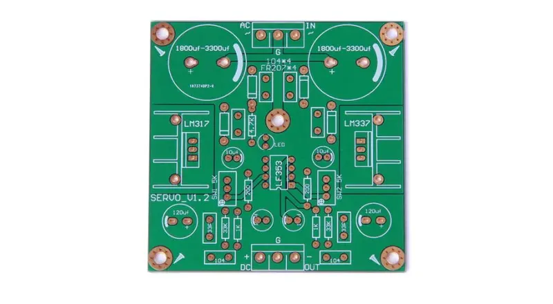
Automotive PCB Assembly for EV and ADAS Systems
With the rapid evolution of electric vehicles (EVs) and Advanced Driver Assistance Systems (ADAS), modern vehicles have transformed into highly complex electronic ecosystems. Achieving optimal performance requires specialized automotive PCB assembly capable of withstanding extreme environmental stresses. This comprehensive guide breaks down the critical standards and technical requirements for automotive PCBA—including IATF 16949 certified manufacturing , AEC-Q100/Q200 component qualifications , EV Battery Management System (BMS) architectures , and PPAP process validation —ensuring zero-defect reliability from prototype to production.
Driving the Future of Mobility
As the automotive landscape shifts towards electrification and autonomous driving, the vehicle has evolved from a mechanical system to a complex electronic ecosystem. You have arrived here because you understand that modern mobility demands more than just standard circuits — it requires “Engineering for Every Environment.”
At NextPCB, we bridge the gap between automotive innovation and manufacturing reality. Unlike consumer electronics, automotive PCBs function as the critical nervous system of the vehicle, requiring absolute precision in processing, sensing, and power management. From the powertrain to the infotainment system, our automotive PCB assembly solutions are built to withstand extreme vibrations, thermal fluctuations, and rigorous safety standards.
The Dual Demand: Safety and Performance in Automotive Electronics
The electronics content of a modern battery electric vehicle (BEV) can exceed 3,000 individual electronic components spread across dozens of ECUs. ADAS-equipped platforms add another layer of complexity: radar sensors operating at 77 GHz, camera processors handling real-time image streams, and LiDAR units generating point clouds that demand millisecond-level response latency. Each of these systems places a distinct set of requirements on the underlying PCB assembly — requirements that cannot be satisfied by the same processes used for consumer devices.
Three structural differences define automotive PCBA compared to standard commercial electronics:
Operational life expectancy. Consumer electronics typically target 3–5 years of service. An automotive ECU is expected to function reliably for 10–15 years, across temperature cycles that range from a cold winter start at −40 °C to underhood steady-state temperatures exceeding 125 °C.
Zero-defect tolerance. A failed capacitor in a smartphone is a warranty claim. A failed component in an electronic power steering unit or an ADAS braking controller is a safety event. This asymmetry drives an entirely different approach to inspection, traceability, and process control.
Regulatory and supply chain discipline. Every component, every solder joint, every process parameter must be documentable to an auditable standard — from raw laminate to finished board. This is not optional; it is the baseline expectation of Tier 1 suppliers and OEMs.
Understanding these demands is the starting point for any automotive PCBA discussion.
Matching Our Capabilities to Your Automotive Needs
Drawing from our Advanced PCB capabilities and PCB Assembly capabilities, we provide tailored solutions for specific automotive systems. Here is how NextPCB supports your engineering challenges:
| Automotive System |
Key Technology |
NextPCB Capability |
| EV Powertrain & BMS (Battery Management) |
High Current & Thermal Dissipation |
Heavy Copper PCBs (up to 10 oz) and Metal Core PCBs for superior heat management |
| ADAS & Sensors (Radar, LiDAR, Cameras) |
High Speed & Signal Integrity |
HDI (High Density Interconnect) and High-Frequency materials (Rogers, Teflon) for precise data transmission |
| ECU & Control Modules |
Compact Design & Reliability |
Rigid-Flex PCBs and multilayer boards (up to 32 layers) to fit tight spaces without compromising durability |
IATF 16949: The Quality Standard That Opens the Automotive Supply Chain
IATF 16949:2016 is the automotive industry’s unified quality management system standard, developed by the International Automotive Task Force and built on the ISO 9001 framework. Holding this certification is a prerequisite — not a differentiator — for any manufacturer seeking to supply Tier 1 customers directly. Without it, a factory does not enter the conversation.
What makes IATF 16949 substantively different from a general ISO 9001 audit is the emphasis on defect prevention over defect detection, and on supply chain control rather than incoming inspection. The standard requires documented control plans, failure mode and effects analysis (FMEA), statistical process control (SPC) at critical production steps, and a formal process for managing customer-specific requirements (CSRs) from each OEM.
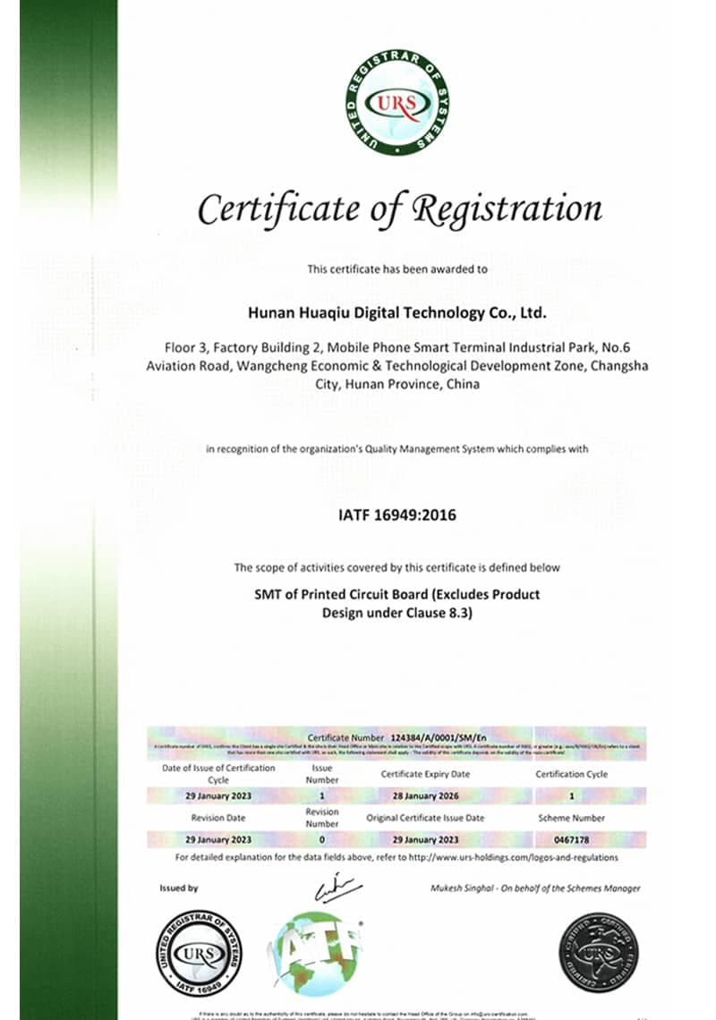
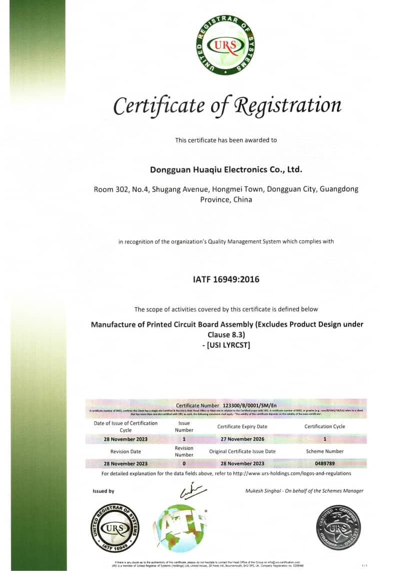
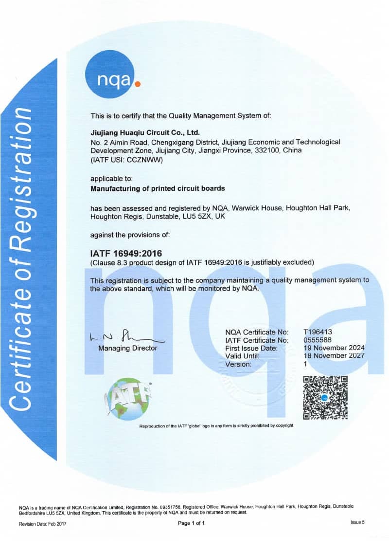
NextPCB holds IATF 16949:2016 certification across its manufacturing network:
- Hunan Huaqiu Digital Technology Co., Ltd. (Changsha) — certified for SMT (Surface Mount Technology) of printed circuit boards
- Dongguan Huaqiu Electronics Co., Ltd. — certified for the manufacture of printed circuit board assemblies (PCBA)
- Jiujiang Huaqiu Circuit Co., Ltd. — certified for printed circuit board fabrication, providing the upstream substrate for automotive assembly runs
The certification scope explicitly excludes product design (per Clause 8.3), which means the quality system is focused entirely on process control for customer-provided designs — consistent with how Tier 1 and Tier 2 suppliers operate.
These factories simultaneously hold ISO 9001:2015, ISO 14001:2015 (environmental management), and ISO 13485:2016 (medical device quality management). The overlap with medical standards is not incidental: both automotive and medical applications demand Class 3 workmanship levels, full lot traceability, and controlled handling of electrostatic-sensitive devices. A facility accredited under both frameworks demonstrates a manufacturing discipline that goes beyond any single vertical.
- Key certification fact for procurement teams: When requesting IATF 16949 documentation, ask for the certificate scope statement. It should explicitly list “PCB assembly” or “PCBA manufacturing” — not just PCB fabrication — to confirm the assembly process itself is covered.
AEC-Q100 and AEC-Q200: Component Qualification at the Heart of Automotive Reliability
The Automotive Electronics Council (AEC) qualification standards define the stress testing a component must survive before it can be considered suitable for automotive-grade use. Specifying AEC-Q qualified parts in the BOM is one of the most consequential decisions in automotive PCB design — and one of the most frequently underestimated by teams transitioning from industrial or consumer backgrounds.
AEC-Q100 covers integrated circuits (ICs). Components are divided into temperature grades that determine the ambient operating range:
| AEC-Q100 Grade |
Min Operating Temp |
Max Operating Temp |
Typical Placement |
| Grade 0 |
−40 °C |
+150 °C |
Under-hood, near engine/transmission |
| Grade 1 |
−40 °C |
+125 °C |
Passenger compartment, general ECU |
| Grade 2 |
−40 °C |
+105 °C |
Interior, non-powertrain |
| Grade 3 |
−40 °C |
+85 °C |
Passenger cabin, infotainment only |
Qualification testing at each grade includes accelerated temperature cycling, high-temperature operating life (HTOL), electrostatic discharge (ESD), and humidity bias testing, among others. A component that passes AEC-Q100 Grade 1 cannot simply be substituted with a commercial-grade equivalent claiming the same datasheet operating range — the qualification testing process validates reliability under combined stress conditions that datasheets alone do not capture.
AEC-Q200 applies to passive components — resistors, capacitors, inductors, and filters — using equivalent temperature grade definitions. Passive components are often overlooked in automotive qualification reviews, yet ceramic capacitors in particular can exhibit significant capacitance loss under DC bias (the DC bias effect on Class II ceramics) and under low-temperature conditions. AEC-Q200 qualification includes electrical characterization across the full temperature range and mechanical shock testing.
AEC-Q101 covers discrete semiconductors (diodes, transistors, MOSFETs), completing the three-standard framework that covers the majority of components on an automotive PCB BOM.
When NextPCB reviews a BOM for automotive PCBA orders, component qualification grade verification is part of the DFM and DFA analysis process. Parts not listed with AEC-Q qualification should be flagged before production — substituting non-automotive-grade components to manage availability is a common source of field failures that traces back to BOM management decisions made before the board was ever assembled.
EV Battery Management System PCB Assembly
The Battery Management System (BMS) is the intelligence layer of an electric vehicle’s energy storage architecture. Its PCB must simultaneously monitor cell voltages at millivolt resolution, balance charge across hundreds of cells, communicate with the vehicle’s powertrain controller, and trigger protection circuits fast enough to prevent thermal runaway events — all within a high-voltage environment that imposes strict isolation requirements.
Electrical Isolation and Creepage Distance
A BMS PCB operating in a high-voltage pack (400 V or 800 V platform) must maintain defined creepage and clearance distances between the high-voltage measurement circuitry and the low-voltage control side. IPC-2221B provides the foundational guidelines, but automotive BMS designs commonly reference IEC 62368-1 or OEM-specific electrical safety requirements layered on top. PCB layout must preserve these isolation zones through assembly — conformal coating, board cutouts, and component placement restrictions all need to be defined in the manufacturing drawing.
Thermal Management in BMS Substrates
Sustained current draw through cell balancing resistors and protection FETs generates localized heat that must be conducted away from the PCB surface. For high-power BMS modules, copper base metal core PCBs and aluminum substrates are the common solutions, both of which NextPCB manufactures. Heavy copper PCBs (up to 10 oz copper weight) are used where current-carrying capacity on the power traces is the primary driver. The surface finishes compatible with automotive soldering requirements — ENIG (Electroless Nickel Immersion Gold) and OSP (Organic Solderability Preservative) — are both available and have different implications for shelf life and reflow process windows that should be discussed with the assembly team during DFM review.
Material Selection for BMS Boards
High-Tg (glass transition temperature) laminates are required for BMS PCBs that will experience sustained elevated temperatures. Standard FR-4 (Tg ≈ 130–140 °C) is insufficient for Grade 0 or Grade 1 temperature profiles. High-Tg FR-4 materials (Tg > 170 °C) and halogen-free laminates are stocked at NextPCB’s facilities, meeting both the thermal stability requirements and the environmental compliance requirements (RoHS, REACH) that automotive OEMs increasingly specify at the contract level.
ADAS Sensor PCB Assembly Requirements
Advanced Driver Assistance Systems introduce a category of PCB assembly challenge that is fundamentally different from power electronics: the challenge is not heat management but signal integrity at frequencies where the physical geometry of a solder joint becomes a circuit element.
Radar PCB Constraints (77 GHz)
Automotive radar front-end modules operating at 76–81 GHz use microstrip or coplanar waveguide transmission lines where trace width tolerances of ±25 µm directly affect impedance matching and, consequently, antenna radiation efficiency. The laminate material for these boards is typically a low-loss, stable-Dk material such as Rogers RO4003C or RO4350B. Assembly of radar PCBs requires:
- Controlled paste deposition volume at fine-pitch antenna feed pads
- Reflow profile validation to avoid warpage of the thin laminate
- Post-reflow impedance verification
NextPCB’s HDI capability and access to controlled-impedance fabrication — with inner layer minimum line widths down to 2.5/3.0 mil — supports the fine-geometry requirements of ADAS radar front-end boards.
Camera and Image Processor PCBs
The image processing pipeline in a surround-view or front-facing camera system uses high-speed serializer/deserializer (SerDes) interfaces, typically GMSL or FPD-Link III, running at multi-gigabit speeds. PCB stack-up design for these interfaces requires controlled differential pair impedance (typically 100 Ω), with consistent dielectric thickness tolerance across the panel to hold impedance within ±10 %. Any impedance discontinuity at a via, connector footprint, or reference plane split becomes visible as signal reflections at these data rates.
X-Ray inspection is particularly relevant for ADAS processing boards that use BGAs or LGAs, where the solder joint beneath the package is not accessible to AOI. BGA solder void percentage, ball coplanarity, and bridging defects can only be reliably detected through 2D or 3D X-Ray analysis. NextPCB applies X-Ray inspection as part of the automotive assembly quality process for packages where AOI coverage is insufficient.
Solder Alloys and Thermal Cycling Reliability
Lead-free soldering is standard practice under RoHS compliance, and the most widely used alloy in automotive assembly is SAC305 (Sn 96.5% / Ag 3.0% / Cu 0.5%), with a melting point of approximately 217–220 °C. SAC305 offers a good balance of thermal fatigue resistance, joint strength, and process compatibility with standard reflow equipment.
However, specific automotive applications push the limits of SAC305 performance:
| Application Condition |
Concern |
Alternative Alloy Consideration |
| Grade 0 underhood (−40 to +150 °C cycling) |
Thermal fatigue crack propagation in SAC305 |
High-Ag alloys (SAC405, SAC0307 + dopants); solders with added Bi or Sb |
| Rework of BGA components |
Minimizing thermal stress to adjacent components |
Lower-temp rework pastes; selective heating |
| Connector pin soldering (wave/selective) |
Through-hole barrel fill and fillet consistency |
SAC305 wave solder with adjusted bath temperature |
| Conformal coating adhesion |
Surface energy of as-soldered finish |
Cleaning residue flux before coating (no-clean flux compatibility must be verified) |
The reflow profile for automotive boards must be validated against both the thermal requirements of the solder alloy and the component-level maximum reflow temperature specifications, which for AEC-Q qualified parts may differ from their commercial counterparts. Process validation records — including solder paste inspection (SPI) data, reflow profile logs, and AOI rejection rates — form part of the documentation package in the PPAP submission.
Mechanical Reliability: Vibration, Shock, and Environmental Protection
An under-dash ECU or a camera module mounted at the A-pillar experiences continuous vibration across a frequency range that depends on road surface, powertrain noise, and acoustic resonances of the vehicle body. ISO 16750-3 defines the environmental conditions and test requirements for mechanical loads on electrical equipment in road vehicles. PCB assembly design for vibration resistance addresses several areas:
Component mass and lead compliance. Heavy components — large aluminum electrolytic capacitors, power inductors, connector housings — should be supported by both soldering and mechanical retention (clips, adhesive, or press-fit). During assembly, these components require controlled insertion force and position verification.
Via and pad integrity under flex. PCBs that are flexed during installation or that experience repeated thermal cycling expand and contract at rates determined by the CTE (coefficient of thermal expansion) of the laminate. Blind/buried vias and microvias in HDI boards have smaller barrels and are more susceptible to barrel cracking under thermal fatigue than through-hole vias. Via fill and capping strategies during PCB fabrication reduce this risk.
Conformal coating for automotive environments. Moisture, condensation, and corrosive agents from road spray require protection beyond the solder joint surface. Acrylic, silicone, and polyurethane conformal coatings each have different temperature resistance profiles, application methods, and rework characteristics. For assemblies that must be repaired in the field, acrylic coatings are more amenable to localized removal than polyurethane or epoxy. The coating process — spray, selective spray, or dip — affects coverage uniformity and must exclude connector contacts, test points, and components with vent holes. NextPCB’s PCBA process includes conformal coating as an available finishing step for automotive programs requiring environmental protection.
PPAP and Process Validation: Documenting That the Process Works
The Production Part Approval Process (PPAP) is the formal mechanism by which an automotive supplier demonstrates to a customer that its manufacturing process is capable of consistently producing conforming parts at production volume. PPAP originated in the North American automotive supply chain and is now globally required through IATF 16949 customer-specific requirements.
A complete PPAP submission contains 18 elements. The most technically substantive for PCBA manufacturing include:
| PPAP Element |
Relevance to PCBA |
| Design Records |
Customer Gerber, BOM, assembly drawings — version-controlled |
| Process Flow Diagram |
SMT paste → placement → reflow → AOI → THT → wave/selective → X-Ray → test sequence |
| Process FMEA |
Failure mode analysis for paste bridging, tombstoning, BGA voids, solder cold joints |
| Control Plan |
Inspection frequency, measurement method, reaction plan for each process step |
| Measurement System Analysis (MSA) |
Gage R&R studies on AOI systems, SPI measurement equipment |
| Initial Process Capability Studies |
Cpk ≥ 1.67 required for new characteristic submissions; Cpk ≥ 1.33 for ongoing |
| Qualified Laboratory Documentation |
Certification of test labs used for functional testing or environmental testing |
| Sample Parts |
Physical production-intent samples at the submission level requested |
| Part Submission Warrant (PSW) |
Authorized sign-off document confirming all elements are complete |
PPAP submissions are categorized into five levels, with Level 3 (full submission to customer) being the most common for new programs. Level 1 (PSW only, retained at supplier) and Level 2 (PSW with designated samples) are used for less critical parts or ongoing production.
For engineering teams at the prototype and DVT stage, PPAP documentation may feel premature. However, starting process validation activities — SPI data collection, reflow profile logging, AOI rejection tracking — during pilot builds significantly reduces the effort required to compile a PPAP submission at production launch. NextPCB supports Rev 0 rapid PCBA prototyping from 7 working days, and the DFM/DFA analysis performed at the prototype stage generates documentation that carries forward into the process validation record.
>> Recommend reading: Automotive PCB Design: IPC-6012DA, AEC-Q200 and What Makes Car-Grade Boards Different
Why NextPCB Is Your Trusted Automotive PCB Assembly Partner
In the automotive industry, a defect is not just an error — it is a safety risk. NextPCB’s manufacturing philosophy is aligned with the zero-defect discipline that Tier 1 automotive supply chains require.
IATF 16949 Certified across the production network. Both the Changsha SMT facility and the Dongguan PCBA facility hold IATF 16949:2016 certification, with the Jiujiang PCB fabrication plant providing the upstream substrate under the same quality standard. This means the quality system is continuous from bare laminate to finished assembly.
Full-cycle inspection: AOI, SPI, and X-Ray. Automated Optical Inspection is applied after paste printing and after reflow. X-Ray inspection is available for BGA, LGA, and other bottom-terminated packages. Solder Paste Inspection (SPI) validates paste volume and placement before components are committed to the board — the point where corrections are least costly.
Environmental compliance documented. RoHS compliance is verified and certified. REACH screening for substances of very high concern (SVHC) confirms concentrations at or below 0.1% (w/w). PFAS testing is available for programs with fluoropolymer-free material requirements. These certifications are available in documentation form for OEM qualification packages.
Turnkey service from prototype to production. From rapid prototyping — supporting Rev 0 PCBA builds as fast as 7 working days — through production scaling, NextPCB handles component sourcing, PCB fabrication, SMT assembly, selective soldering, conformal coating, functional testing, and shipping in a single managed workflow. Advanced DFM and DFA analysis is performed before production begins, surfacing issues that would otherwise generate ECOs or scrap at the first article stage.
Frequently Asked Questions
Q: What is IATF 16949, and why does it matter for automotive PCB assembly?
IATF 16949:2016 is the global quality management system standard developed specifically for automotive supply chain manufacturers. It extends ISO 9001 with automotive-specific requirements: defect prevention controls, FMEA, statistical process control, and documented customer-specific requirement management. Holding this certification confirms that a manufacturer’s processes — not just its products — meet the discipline required by OEMs and Tier 1 suppliers. Without it, most automotive supply chains will not qualify a new vendor.
Q: What is the operating temperature range for automotive-grade PCBs?
The applicable range depends on the AEC-Q100 temperature grade specified for the components. Grade 1 — the most common for general ECU and passenger compartment applications — covers −40 °C to +125 °C. Grade 0 covers −40 °C to +150 °C and applies to underhood locations near the engine or transmission. The PCB laminate, solder alloy, and all passive components must be specified to match the grade required by the most demanding component on the board.
Q: What are AEC-Q100 qualified components?
AEC-Q100 is the Automotive Electronics Council standard that defines the stress testing a semiconductor IC must survive to be considered automotive-grade. Qualification testing includes accelerated temperature cycling, high-temperature operating life, electrostatic discharge, and humidity bias testing, among others. A component carrying AEC-Q100 qualification has been tested to survive these combined stress conditions at the specified temperature grade — not merely rated on a datasheet for the equivalent temperature range.
Q: How are EV BMS PCBs different from consumer electronics boards?
Battery Management System PCBs operate in a high-voltage environment (typically 400 V or 800 V battery packs) and must maintain defined electrical isolation distances between cell measurement circuitry and low-voltage control logic. They require high-current carrying capacity on power traces (addressed through heavy copper or metal core substrates), thermal management for cell balancing and protection switching elements, and reliability over a 10–15 year vehicle service life. Consumer electronics boards share none of these constraints.
Q: What is PPAP in the context of automotive PCB manufacturing?
PPAP — Production Part Approval Process — is the formal documentation and approval procedure by which an automotive supplier demonstrates that its manufacturing process can consistently produce conforming parts at production volume. A complete PPAP submission includes process flow diagrams, process FMEA, control plans, initial process capability studies (Cpk), measurement system analyses, and physical sample parts. It is required by IATF 16949 customer-specific requirements and is submitted at defined levels of completeness depending on customer requirements and part criticality.
Ready to Discuss Your Automotive PCBA Project?
NextPCB provides the certification framework, material capability, and assembly discipline that automotive electronics programs require — from first prototype through production ramp.
Get an Automotive PCBA RFQ — IATF 16949 Certified →
Inquire About Turnkey Automotive PCB Assembly →
Looking for More PCB Solutions Across Industries?
Whether it’s for electric vehicles (EVs), medical devices, or industrial applications, NextPCB provides engineering-grade solutions tailored to your requirements. Back to Industry Hub →
Related PCB Application Industries


 NextPCB Capabilities
 PCB Assembly
 Layer Buildup
 SMD-Stencils
 PCB Design-Aid & Layout
 Mechanics
 Quality
 Drills & Throughplating
 Factory & Certificate
 PCB Assembly Factory Show
Certificate
PCB Assembly Factory Show
Certificate
 NextPCB Capabilities
 PCB Assembly
 Layer Buildup
 SMD-Stencils
 PCB Design-Aid & Layout
 Mechanics
 Quality
 Drills & Throughplating
 Factory & Certificate