
 NextPCB Capabilities
Printed Circuit Boards
NextPCB Capabilities
Printed Circuit Boards
 PCB Assembly
 Layer Buildup
 SMD-Stencils
 PCB Design-Aid & Layout
 Mechanics
 Quality
 Drills & Throughplating
 Factory & Certificate
 PCB Assembly Factory Show
Certificate
PCB Assembly Factory Show
Certificate

Support Team
Feedback:
support@nextpcb.com


In high-speed digital, RF communications, satellite communications, radar, and microwave systems, PCB materials no longer serve merely as substrates that "provide mechanical support and insulation." When signal frequencies enter the GHz range, dielectric constant (Dk), dissipation factor (Df), dielectric constant stability, and frequency-dependent material characteristics directly impact signal integrity, impedance control, and overall system performance. Even small fluctuations in the dielectric constant (Dk) and the cumulative effect of dielectric loss (Df) can directly render carefully designed impedance matching useless. Among many high-frequency PCB materials, the Rogers RT5880, with its Dk=2.20±0.02 and Df=0.0009@10GHz specifications, is regarded by countless RF engineers as a benchmark for low-loss high-frequency substrates, particularly suited for RF and microwave circuits that demand superior high-frequency performance and low dielectric loss.
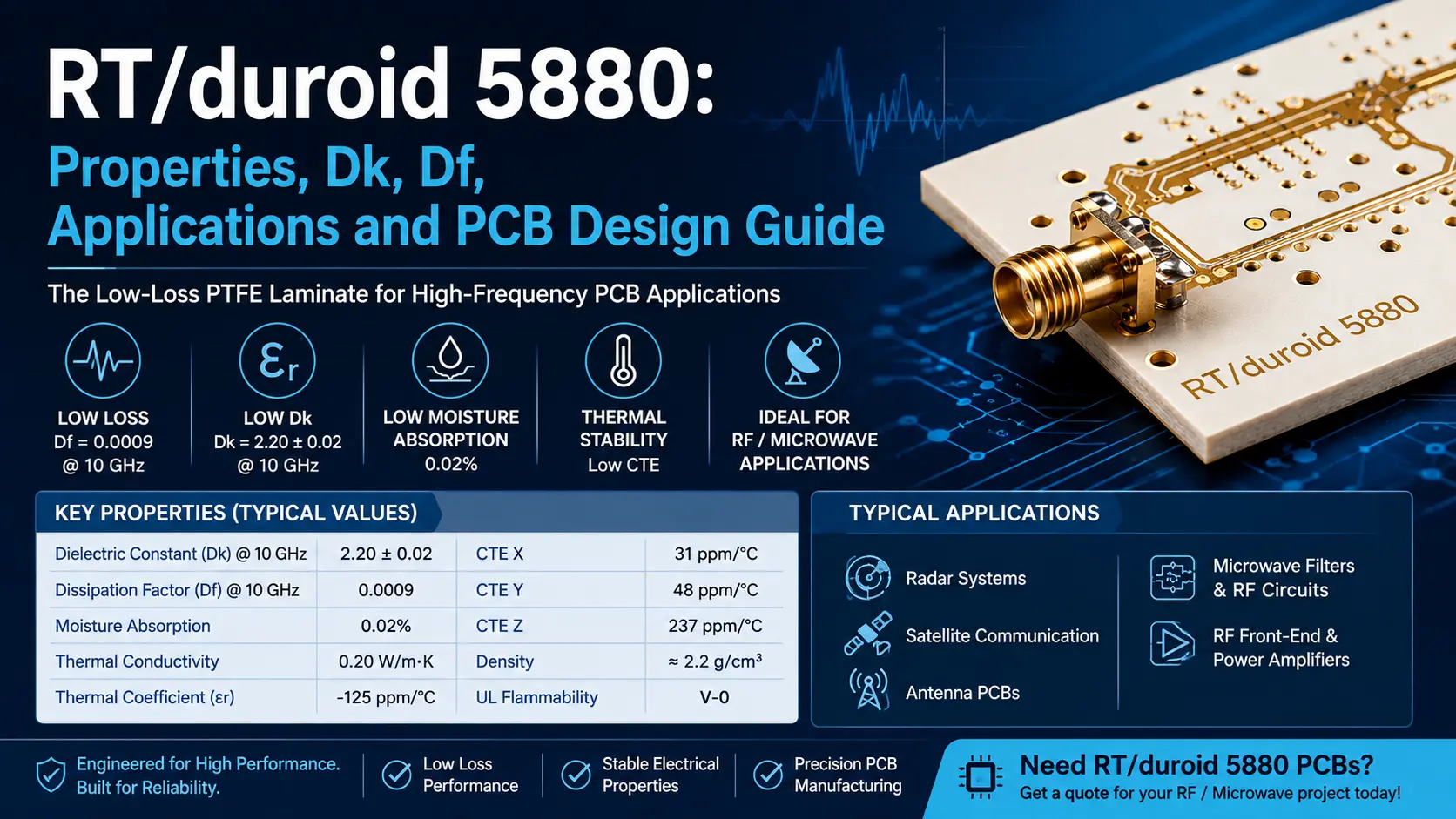
Rogers RT5880 (also known as Duroid 5880) is a glass-microfiber-reinforced polytetrafluoroethylene (PTFE / Teflon) composite material.
Unlike conventional woven glass fabric–reinforced PCB materials, RT/duroid 5880 employs randomly oriented glass microfibers to reinforce the PTFE matrix, improving dielectric constant consistency across different orientations.
According to Rogers' official datasheet, RT5880 features an extremely low dielectric constant (Dk = 2.2) and an industry-leading ultra-low dissipation factor (Df ≈ 0.0009 at 10 GHz), making it the industry gold standard for high-frequency circuit design.
Among the many high-frequency PCB materials available, Rogers RT5880 is a classic low-loss PTFE-based high-frequency laminate, particularly well-suited for RF/microwave circuits that demand superior high-frequency performance and minimal dielectric loss. However, the PTFE matrix is mechanically soft and highly sensitive to thermal stress, resulting in processing characteristics that differ fundamentally from conventional FR-4. Entrusting such specialty boards to low-cost, quick-turn PCB shops unfamiliar with PTFE processing often leads to glass-fiber tearing during drilling, poor copper adhesion, and dimensional instability, potentially rendering entire batches unusable prior to delivery.
Evaluating a high-frequency PCB material requires more than a single Dk value. For RF and microwave PCB design, the following parameters must be considered collectively: Dk, Df, moisture absorption, coefficient of thermal expansion (CTE) in all three axes, thermal conductivity, copper foil type, and dielectric constant variation with frequency and temperature.
The following table summarizes the key typical parameters of RT/duroid 5880:
| Parameter | RT/duroid 5880 | Design/Manufacturing Implication |
|---|---|---|
| Dielectric Constant Dk @ 10 GHz | 2.20 ± 0.02 | Use 2.20 directly for impedance calculation; no correction factor required |
| Design Dk | 2.20 | — |
| Dissipation Factor Df @ 10 GHz | 0.0009 | Critical enabler for millimeter-wave link budget closure |
| Thermal Coefficient of εr (TCDk) | -125 ppm/°C | Negative and linear temperature drift enables predictable phase behavior over wide temperature ranges |
| Moisture Absorption | 0.02% | Suitable for satellite and outdoor radar applications in high-humidity environments |
| Thermal Conductivity | 0.20 W/m·K | Weak thermal dissipation; not recommended for high-power amplifiers |
| CTE X | 31 ppm/°C | Must be factored into compensation for large-board designs |
| CTE Y | 48 ppm/°C | Same as above |
| CTE Z | 237 ppm/°C | Primary cause of manufacturing failures; approximately 5× that of FR-4 |
| Density | ≈ 2.2 g/cm³ | — |
| UL94 Flammability Rating | V-0 | Meets most application requirements |
What does Z-axis CTE = 237 ppm/°C mean in practice? At the reflow soldering peak temperature of approximately 230°C, the Z-axis expansion is roughly 4 to 5 times that of FR-4. The copper plating on the hole wall is subjected to significant tensile stress. If the ductility of the plated layer is inadequate or the thickness is insufficient, the barrel crack failure rate can reach 3% to 8% during the first reflow pass and increase to 15% to 25% after three reflow cycles. This is a critical reliability constraint that must be acknowledged when specifying RT5880.
In high-frequency circuits, dielectric loss is generated when signals propagate through the PCB dielectric. The lower the Df, the smaller the energy loss caused by the dielectric to high-frequency signals. The Df of RT5880 at 10 GHz is 0.0009, which is about 1/20 of FR-4 (on the order of 0.02). At 28 GHz, the proportion of dielectric loss in the total insertion loss is about 40% to 60% (depending on the trace width and copper foil type), which makes RT5880 particularly suitable for:
For RF / Microwave designs that need to reduce insertion loss and improve transmission efficiency, low Df is one of the core advantages of RT5880.
The design Dk of RT5880 is 2.20. More importantly, Rogers specifically emphasizes that its randomly oriented glass microfiber structure helps maintain good Dk consistency.
Why is Dk consistency important? Because the signal propagation speed, impedance, and transmission line dimensions in a PCB are all related to the dielectric constant.
For microstrip or stripline, changes in the material Dk will affect:
Therefore, for GHz-grade circuits, the stability and uniformity of Dk are often more important than simply a "low Dk." RT5880 controls the Dk tolerance within ±0.02 and remains flat across the entire frequency band from 1 MHz to 10 GHz, which is the core reason why it is written into the selection lists for military radar and satellite communications.
FR-4 is the most common PCB substrate, while RT/duroid 5880 is optimized for high-frequency applications. The distinction is not about which material is "better"—it is about differing application targets.
| Comparison Parameter | FR-4 | RT/duroid 5880 |
|---|---|---|
| Material System | Epoxy resin/woven glass fabric | PTFE/glass microfiber composite |
| Typical Applications | General-purpose digital/electronic circuits | RF/Microwave |
| High-Frequency Loss | Relatively high (Df ≈ 0.02) | Ultra-low (Df = 0.0009) |
| Dk | Higher, varies with frequency/temperature | ≈ 2.20, stable across frequency |
| High-Frequency Impedance Control | More challenging | Better suited |
| PCB Cost | Lower | Significantly higher (approx. 10–15×) |
| Processing Difficulty | Relatively straightforward | More demanding; relies on PTFE process expertise |
| High-Frequency Suitability | Limited | Excellent |
Not every PCB requires Rogers 5880. For conventional MCU-based designs, digital control boards, and power supplies, FR-4 is typically sufficient. However, for circuits operating at higher frequencies with stringent requirements for insertion loss, impedance, and phase consistency, RT/duroid 5880 offers a clear advantage.
RT5880 is primarily oriented toward high-frequency, microwave, and broadband applications, and has been batch-deployed in high-reliability commercial and military scenarios:
Although RT/duroid 5880 has outstanding high-frequency performance, it is not a simple substitute for standard FR-4. Special attention must be paid to the following aspects during PCB design and manufacturing.
High-frequency PCBs usually require strict control of characteristic impedances such as 50Ω, 75Ω, 90Ω, and 100Ω differential. When designing, you cannot simply apply the trace width experience of FR-4.
The Dk of RT5880 is approximately 2.20, and the final trace width is also affected by factors such as dielectric thickness, copper thickness, copper foil roughness, trace etching, stack-up structure, and solder mask. Therefore, impedance design should be calculated and verified in combination with the actual PCB stack-up and manufacturer capabilities.
In high-frequency PCBs, the surface roughness of the copper foil directly affects high-frequency signal loss. The higher the frequency, the more pronounced the skin effect becomes, concentrating current on the conductor surface. Therefore, for high-frequency applications, you cannot look at copper foil types simply by "1 oz / 2 oz." You also need to pay attention to:
Rogers' official documentation indicates that RT/duroid 5880 can use different types and weights of copper foil, and recommends specifying the dielectric thickness, thickness tolerance, copper foil type, and copper thickness when ordering.
Although RT5880 has outstanding high-frequency performance, the PCB manufacturing process for PTFE materials is not entirely the same as that for standard FR-4. Special attention must be paid to the following aspects:
Material Processing
Rogers' official documentation indicates that RT5880 can be cut, sheared, and mechanically machined while maintaining good chemical resistance. However, in actual PCB manufacturing, appropriate processing parameters still need to be selected based on board thickness, copper thickness, hole diameter, and structure.
Drilling
The mechanical properties of PTFE-based materials differ from those of FR-4, so:
all need to be controlled by a PCB factory familiar with high-frequency materials.
Pretreatment for Hole Metallization
The water contact angle of untreated PTFE surfaces is about 110°, making it impossible for electroless copper plating solutions to wet them. Plasma activation (oxygen/carbon tetrafluoride mixed atmosphere) or sodium naphthalene chemical treatment must be performed. After treatment, the surface tension of the hole wall must reach 42 dyne/cm or higher before proceeding to the subsequent copper deposition process. PCB factories without this process should not undertake RT5880 orders.
Multi-layer Hybrid Lamination
If the PCB contains both FR-4 and RT5880, special attention must be paid to the CTE, Dk, Df, thermal expansion, lamination parameters, and dielectric thickness between different materials. It is recommended to use low-flow prepregs (such as RO4450F) as transition layers and to lower the reflow soldering peak temperature (recommended < 230°C).
Check PCB Cost Based on Rogers Materials
RT/duroid 5870 and 5880 are frequently compared, as both belong to the glass-microfiber-reinforced PTFE product family. The key differentiators are Dk and Df.
| Parameter | RT/duroid 5870 | RT/duroid 5880 |
|---|---|---|
| Dk @ 10 GHz | 2.33 ± 0.02 | 2.20 ± 0.02 |
| Df @ 10 GHz | 0.0012 | 0.0009 |
| CTE X | 22 ppm/°C | 31 ppm/°C |
| CTE Y | 28 ppm/°C | 48 ppm/°C |
| CTE Z | 173 ppm/°C | 237 ppm/°C |
Data sourced from Rogers published documentation.
Selection guideline: 5880 offers lower Dk and lower Df, emphasizing low loss and low dielectric constant benefits. However, for applications with stringent Z-axis reliability requirements (e.g., aerospace, automotive AEC-Q100) where a Dk of 2.33 is acceptable, 5870 is the more conservative choice due to its lower CTE.
When many engineers first encounter Rogers materials, they will find that for a PCB of the same size, using RT/duroid 5880 may significantly increase costs. The reason is not just that the material itself is more expensive. Costs usually come from several aspects:
Material Cost: PTFE high-frequency laminates themselves are high-performance materials.
Manufacturing Process: RT/duroid 5880 places higher demands on processing, drilling, lamination, copper plating, and dimensional control.
High-Frequency Testing: Some high-frequency PCB projects also require:
Low-Volume Production
RF / Microwave PCBs tend to be prototype, small-batch, and high-value-added products, so the unit manufacturing cost is also higher. Therefore, in PCB design, it is not a matter of "using Rogers everywhere you can." Thus, a more reasonable approach is usually: using high-frequency materials only in the areas that truly require high-frequency performance.
If your project has the following characteristics, then RT/duroid 5880 is worth serious consideration:
Conversely, scenarios not suitable for using RT5880 include:
It is unnecessary to use RT5880 in these scenarios; standard high-performance FR-4 is already sufficient.
RT/duroid 5880 is a classic low-dielectric-constant, low-dielectric-loss PTFE high-frequency PCB material. Its most prominent advantages can be summarized as:
This makes it particularly suitable for applications such as:
However, the advantages of RT/duroid 5880 do not mean it is suitable for every PCB. For high-frequency PCBs, material selection is only the first step, and ultimate performance also depends on:
Therefore, when undertaking a PCB project using RT/duroid 5880, it is recommended to involve the PCB manufacturer in the stack-up, impedance, and manufacturing capability evaluation as early as the design stage, rather than waiting until the Gerber files are completed to consider manufacturing issues.
Q1: Does copper foil roughness affect the high-frequency performance of RT/duroid 5880?
Yes. Above 10 GHz, the skin depth is approximately 0.66 μm. Standard ED copper (roughness ≈ 2 μm) introduces conductor loss that can overwhelm the dielectric loss advantage. For high-frequency designs, rolled copper or ultra-low-roughness reverse-treated copper is recommended.
Q2: Can RT/duroid 5880 be used in multilayer PCBs?
Yes. However, inner layers require browning/black oxide treatment to enhance adhesion, and lamination temperature must be raised to approximately 230°C (compared to 180°C for FR-4). It is strongly recommended that the stack-up be submitted to a PTFE-experienced manufacturer for evaluation prior to tape-out.
Q3: How do I choose between RT/duroid 5880 and RO4003C?
For frequencies >20 GHz in passive circuits (antennas, filters) → RT5880. For frequencies <10 GHz with heat-generating components (e.g., power amplifiers) → RO4003C (thermal conductivity 0.44 W/m·K vs. 0.20 W/m·K for RT5880).
Q4: Where can I source small-quantity samples of RT/duroid 5880?
Rogers authorized distributors (e.g., Tianjin Jingcai, Shanghai Andi) as well as Digi-Key and Mouser offer standard-size cut panels.
Q5: Why is the Z-axis CTE of RT/duroid 5880 so high?
Above the glass transition temperature of PTFE, molecular segmental motion increases, and the randomly oriented microfibers provide no continuous constraint in the Z-axis direction. This is inherent to PTFE-based materials. RT5870 reduces Z-axis CTE to 173 ppm/°C through modified filler loading.
Check PCB Cost Based on Rogers Materials Today and take the guesswork out of your next high-frequency prototype run.
Still, need help? Contact Us: support@nextpcb.com
Need a PCB or PCBA quote? Quote now




