A deep dive into structure, material selection (Aluminum vs. Copper vs. Iron), and design specifications for thermal management in electronics.
- Table of Contents
- 1. What Is a Metal Core PCB (MCPCB)?
- 2. Structure and Anatomy of Metal PCBs
- 3. Aluminum Core PCBs: The Industry Standard
- 4. Copper Core PCBs: High-Performance Solutions
- 5. Iron Core PCBs: Specialized Applications
- 6. Material Comparison: Aluminum vs. Copper vs. Iron
- 7. Procurement and Design Guidelines
- 8. Conclusion
- Get Your Metal Core PCB Quote
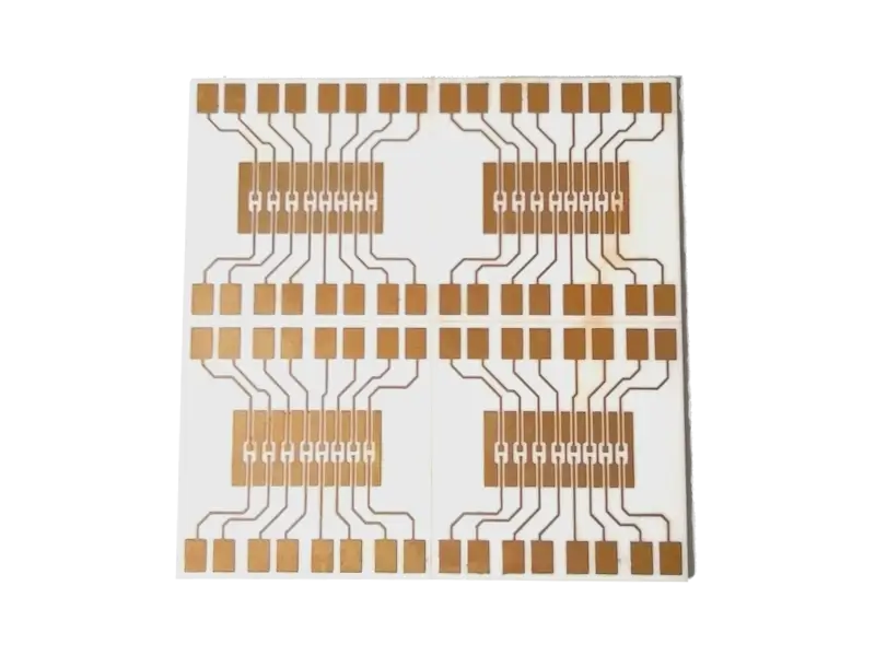
1. What Is a Metal Core PCB (MCPCB)?
A Metal-Core PCB (MCPCB), also known as a Thermal PCB or Insulated Metal Substrate (IMS), is a type of printed circuit board that incorporates a base metal material as the heat spreader portion of the board. The primary purpose of an MCPCB is to redirect heat away from critical board components (such as LEDs or power transistors) and towards a heat sink or the chassis.
Unlike standard FR4 or CEM1-3 boards which are poor thermal conductors, Metal Core PCBs utilize a base metal—typically Aluminum, Copper, or Steel alloy—to significantly improve thermal management, durability, and dimensional stability.
2. Structure and Anatomy of Metal PCBs
The structure of a Metal Core PCB is a trilayer construct. Understanding these layers is crucial for PCB designers to ensure proper impedance control and thermal conductivity.
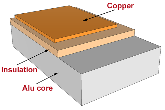
The Three Layers:
- Circuit Layer (Copper Layer): This is the printed circuit foil. It typically ranges from 1.0 oz to 8.0 oz (35μm - 280μm). For high-power applications, thicker copper is used to handle higher current loads. The minimum trace/space is generally around 5/5 mil (0.127/0.127 mm).
- Dielectric Layer (Insulated Layer): This is the most critical layer for thermal performance. It isolates the circuit layer electrically from the metal base while allowing heat to transfer. A high-quality dielectric layer must offer low thermal resistance and high voltage breakdown strength.
- Substrate Layer (Metal Base): This is the backing material (Aluminum, Copper, or Iron) that provides mechanical support and acts as the heat spreader.
3. Aluminum Core PCBs: The Industry Standard
Aluminum is the most commonly used material for MCPCBs due to its balance of cost, weight, and thermal performance. It is easier to machine than copper or steel and significantly lighter.
Common Aluminum Alloys:
- 5052 Alloy: The most popular choice. It offers high thermal conductivity (typically ≥ 2.0 W/m·K) and good mechanical strength. It is suitable for most LED lighting and power supply applications.
- 6063 Alloy: Extremely malleable and often used when the PCB base acts as the chassis itself (extruded aluminum).
- 1001 / 3001 Alloys: Lower cost options with slightly lower thermal conductivity (1.0 W/m·K to 1.5 W/m·K). Suitable for general commercial lighting.
Pricing Factors:
The cost of Aluminum PCBs is primarily driven by:
- Board Thickness: Standard range is 0.6mm to 3.0mm. Thicker boards utilize more raw material and are more expensive.
- Thermal Conductivity (Dielectric): Standard dielectrics (1.0 W/m·K) are cheap. High-performance dielectrics (2.0 - 10 W/m·K) increase the price significantly.
4. Copper Core PCBs: High-Performance Solutions
Copper core PCBs represent the high end of thermal management. While copper is heavier and more expensive than aluminum, its thermal conductivity is far superior (Copper: ~390 W/m·K vs. Aluminum: ~200 W/m·K).
Structure and Variations
Copper substrates are typically manufactured by overlaying insulating resin and copper foil onto a copper base plate via a hot pressing process. Surface finishes can include immersion gold, silver plating, or OSP (Organic Solderability Preservative).
Types of Copper Core Technologies:
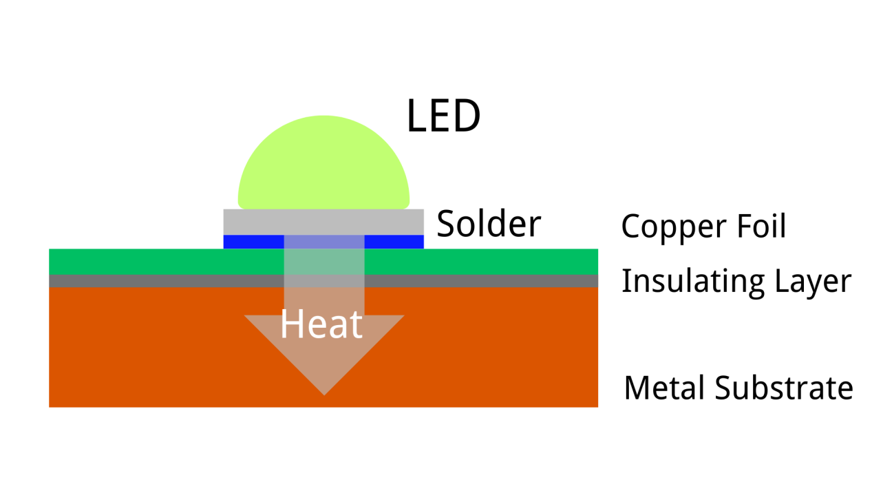
a. Standard Copper Core
Similar to aluminum PCBs, there is a dielectric layer between the circuit copper and the base copper. While better than aluminum, the dielectric layer still acts as a thermal bottleneck.
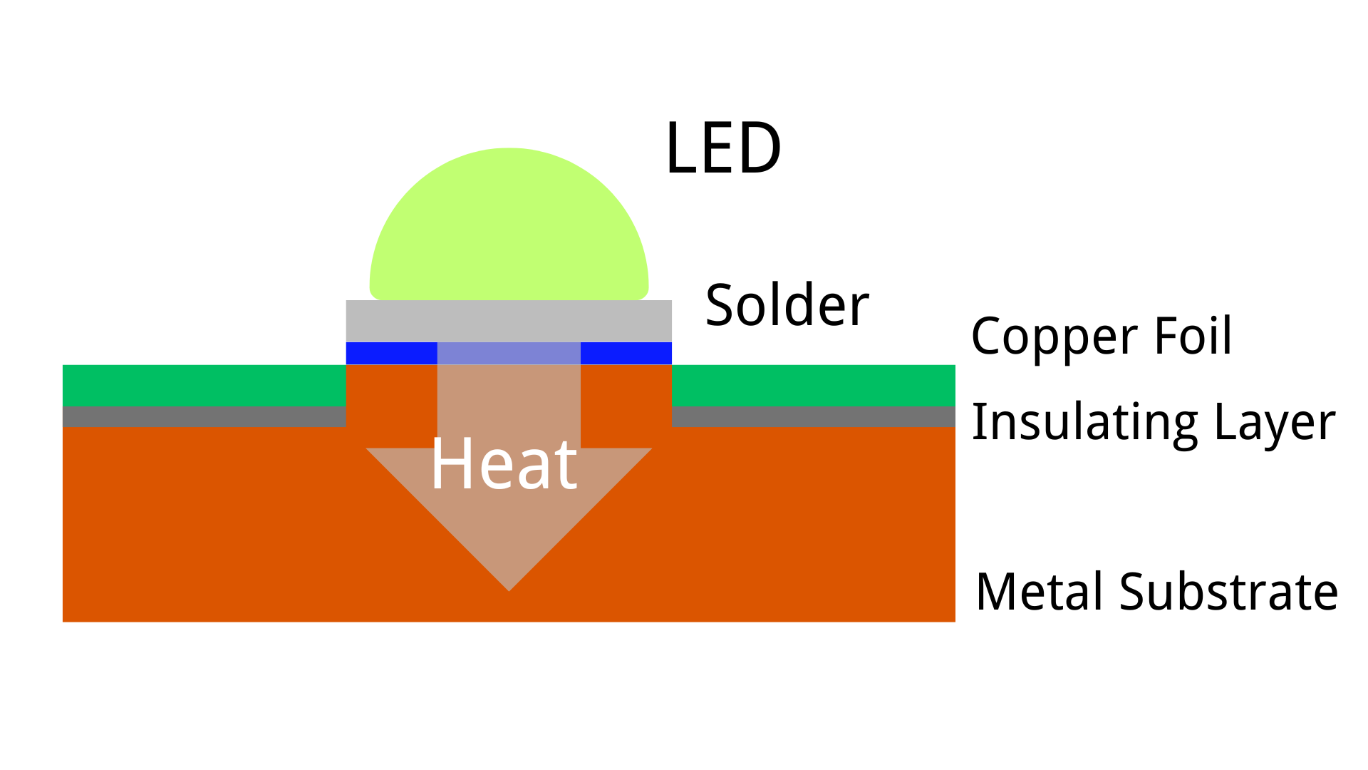
b. Thermoelectric Separation (Direct Thermal Path - DTP)
This is a specialized technology primarily used for high-power LEDs (e.g., Automotive Headlights, UV Curing). In this design, the LED thermal pad connects directly to the copper substrate without an insulating layer in between.
Mechanism: The circuit leads are electrically isolated, but the central thermal pad of the component sits directly on the copper base. This minimizes thermal resistance.
5. Iron Core PCBs: Specialized Applications
Iron-based PCBs (using silicon steel or special steel alloys) replace FR4 or Aluminum in niche applications. The metal thickness usually ranges from 1mm to 6mm.
Key Characteristics:
- Magnetic Properties: Useful for motors and drives where magnetic flux shielding is required.
- Rigidity: Extremely strong mechanically.
- Cost: Low raw material cost, but high processing cost.
Manufacturing Challenges:
Iron core PCBs are difficult to manufacture, leading to scarcity in the supply chain:
- Oxidation: Iron is prone to rust during wet processing (etching/plating), causing delamination of the dielectric layer.
- Machining Difficulty: Iron is harder than copper or aluminum, causing rapid wear on drill bits and routing bits.
- Surface Quality: Ensuring a perfectly flat surface for bonding is difficult, often leading to yield loss.
6. Material Comparison: Aluminum vs. Copper vs. Iron
For procurement managers and engineers, choosing the right substrate is a trade-off between thermal performance, weight, and cost.
| Feature |
Aluminum Core |
Copper Core |
Iron/Steel Core |
| Thermal Conductivity (Substrate) |
Good (~150 - 220 W/m·K) |
Excellent (~380 - 400 W/m·K) |
Poor (~40 - 60 W/m·K) |
| Cost |
Low / Economical |
High |
Medium (High processing cost) |
| Weight |
Light |
Heavy |
Heavy |
| Shielding |
EMI Shielding |
EMI Shielding |
EMI + Magnetic Shielding |
| Primary Application |
General LED Lighting, Audio Equipment |
High-Power Automotive LEDs, CPU/GPU |
Motors, Dynamos |
7. Procurement and Design Guidelines
When requesting a quote (RFQ) or designing a Metal Core PCB, the following specifications must be clearly defined to ensure manufacturability and performance.
Critical Specifications for Manufacturing:
- Thermal Conductivity: Specify the requirements for the dielectric layer. Standard is 1.0 W/m·K. High performance is 2.0, 3.0, or 4.0+ W/m·K.
- Board Thickness: Standard thicknesses are 1.0mm, 1.6mm, and 2.0mm. Non-standard thicknesses increase lead time.
- Copper Weight: 1oz (35μm) is standard. Use 2oz or 3oz for power supplies. Note that heavy copper requires wider trace spacing (etch compensation).
- Surface Finish: HASL (Lead-free) is common for larger pads. ENIG (Immersion Gold) is recommended for wire bonding or fine-pitch components.
- Solder Mask: White solder mask is standard for LED applications to increase reflectivity (Light Reflectivity > 85%).
- Breakdown Voltage (Hi-Pot): Specify the required isolation voltage (e.g., 3000V AC). This is determined by the thickness and quality of the dielectric layer.
8. Conclusion
Metal Core PCBs are the backbone of modern high-power electronics, providing the necessary thermal management to ensure device longevity and efficiency. While Aluminum remains the most versatile and cost-effective choice for general lighting and power applications, Copper offers unmatched performance for demanding automotive and industrial use cases. Iron substrates fill a vital niche where mechanical rigidity and magnetic shielding are paramount. By understanding the unique properties of each material and specifying the correct dielectric parameters, designers can optimize their products for both performance and manufacturability.
Get Your Metal Core PCB Quote
Ready to bring your thermal management designs to life with NextPCB? Whether you need a quick-turn Aluminum prototype or a complex Thermoelectric Separation Copper substrate, selecting the right manufacturing partner is crucial. Ensure your files are ready and your specifications are clear to avoid delays.
Contact us today to discuss your project requirements, upload your Gerber files, and receive a competitive quote tailored to your specific thermal needs.
About the Author
Lolly Zheng- Sales Account Manager at NextPCB.com
Four years of proven sales experience across electronic components and PCBA industries, with strong expertise in key account acquisition, customer relationship management, and contract negotiations. Focused on driving revenue growth through strategic client development and solution-based selling. Experienced in expanding high-value accounts, securing long-term partnerships, and consistently exceeding sales targets in competitive markets.


 NextPCB Capabilities
 PCB Assembly
 Layer Buildup
 SMD-Stencils
 PCB Design-Aid & Layout
 Mechanics
 Surface
 Quality
 Drills & Throughplating
 Factory & Certificate