
 NextPCB Capabilities
Printed Circuit Boards
NextPCB Capabilities
Printed Circuit Boards
 PCB Assembly
 Layer Buildup
 SMD-Stencils
 PCB Design-Aid & Layout
 Mechanics
 Quality
 Drills & Throughplating
 Factory & Certificate
 PCB Assembly Factory Show
Certificate
PCB Assembly Factory Show
Certificate
Support Team
Feedback:
support@nextpcb.com


Centroid file, xy file, pick and place file, position file, component placement file, call it whatever you want, this file contains data that tells automated machines exactly where to place components and how to orient them. At NextPCB, we like to call it the Centroid File. In this article, we cover what a centroid file is and how to export it from various EDA software, including KiCad, Altium Designer, Autodesk Eagle/Fusion, and Sprint Layout.
A centroid file is the set of digital instructions for an automated pick-and-place machine. It is a data file, typically in .csv format, that lists the precise location (X and Y coordinates), rotation, and board side (layer) for every surface-mount component on a PCB, using the component's reference designator. While some EDA software automatically generates this file, others may require manual creation or modification.
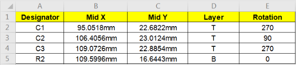
A centroid file contains the following information:
File Formats: .csv, .xls and .xlsx.
Below is a sample centroid file.
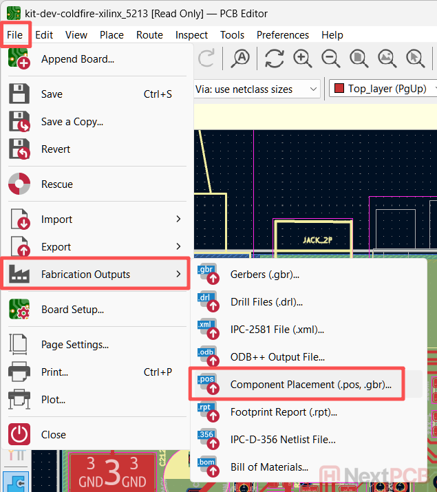
Step 1: Open the .pcb_kicad file and go to File -> Fabrication Outputs -> Component Placement (.pos, .gbr)... or Footprint Position (.pos) File..., depending on your version of KiCad.
Step 2: In the new window, select the Output Directory for the file and click Generate File. This will generate the necessary pick-and-place files.
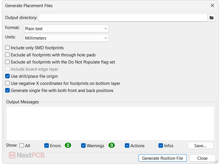
We recommend the above settings for NextPCB's PCBA assembly service. For more information on KiCad's pick-and-place export settings, see our dedicated KiCad article.
Step 3: Package the file into a .rar or .zip archive and upload it to NextPCB's PCBA quotation page for a quote.
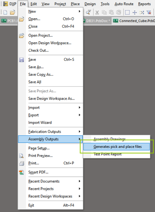
Step 1: In Altium, open the .PCBDoc file and go to Assembly Outputs -> Generates pick and place files.
Step 2: Depending on your version of Altium, you may be able to select which columns to include in your pick and place file. At the very least, we need the Designator, x-y coordinates and the rotation. Other information can be omitted or left as the default values. Altium will generate the file in the same location as the PcbDoc file.
Step 3: Package the file into a .rar or .zip archive and upload it to NextPCB's PCBA quotation page for a quote.
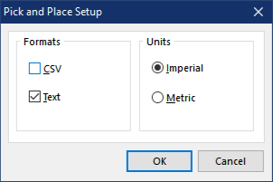
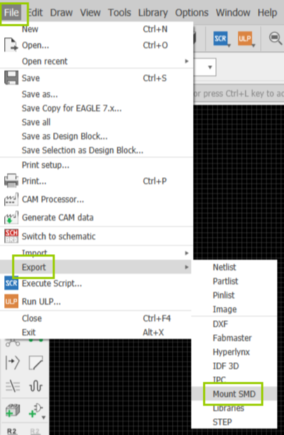
Step 1: In Eagle, open the board layout file (.brd) and go to File -> Export -> Mount SMD.
Step 2: Eagle will then open a Save file dialog asking you where to save the top and bottom pick-and-place files consecutively. The .mnt file is for the top side and the .mnb file is for the bottom side. Package these into a single .rar or .zip file and upload them to NextPCB's PCBA quotation page for a quote.
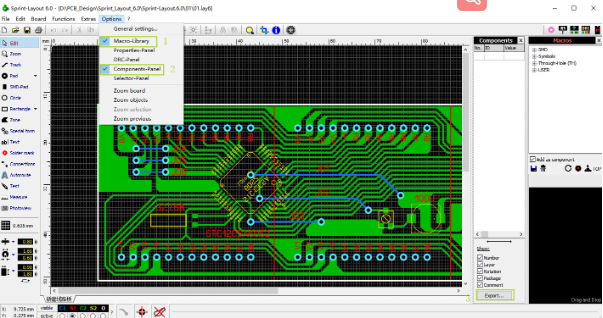
Step 1: Open the PCB layout and go to Options -> Components-Panel to show the component data on the right.
Step 2: Click the Export button at the bottom of the Components-Panel.
Step 3: In the new window, check all the options under Exported Data and click Export....
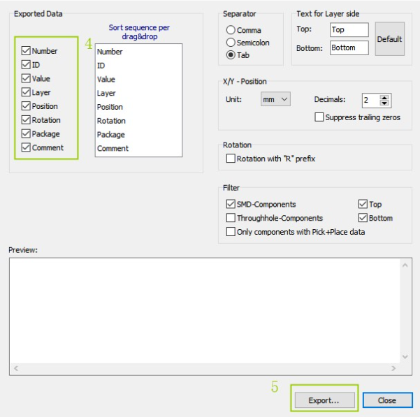
Step 4: Select a location to save your pick-and-place file.
Step 5: Package the file into a .rar or .zip archive and upload it to NextPCB's PCBA quotation page for a quote.
Can't find your tool? Request guidance in the comments section below.
>> Read more: How to Prepare PCB Files for Assembly: Gerber, BOM, Stackup & More
Still, need help? Contact Us: support@nextpcb.com
Need a PCB or PCBA quote? Quote now


 Surface

