
 NextPCB Capabilities
Printed Circuit Boards
NextPCB Capabilities
Printed Circuit Boards
 PCB Assembly
 Layer Buildup
 SMD-Stencils
 PCB Design-Aid & Layout
 Mechanics
 Quality
 Drills & Throughplating
 Factory & Certificate
 PCB Assembly Factory Show
Certificate
PCB Assembly Factory Show
Certificate
Support Team
Feedback:
support@nextpcb.com


Designing a custom PCB for your Arduino project is one of the most rewarding steps in electronics. Instead of relying on breadboards or off-the-shelf shields, a custom Arduino PCB gives you full control over size, component placement, and functionality — and getting it manufactured is faster and more affordable than ever.
In this guide, you'll learn everything you need to know: from laying out your first Arduino PCB to ordering a professional prototype in just a few days.
>> Learn Arduino Uno vs. Mega vs. Micro: Main Differences
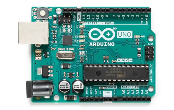
Originating in Italy in 2005, the Arduino is a widely popular programmable microcontroller board with over a decade of history shaping the maker movement. Unlike traditional, bare-bones microcontroller development boards, an Arduino comes pre-integrated with all the essential electronic components—such as capacitors, resistors, crystal oscillators, and voltage regulators—allowing it to operate right out of the box. It supports a broad range of input voltages and breaks out simple, accessible I/O pins, making it incredibly friendly for quick breadboard prototyping and plug-and-play expansion shields. Rather than being cluttered with built-in peripherals like 7-segment displays, keypads, or buzzers, the Arduino maintains a compact, versatile form factor that is easy to embed into custom projects.
A defining feature of the Arduino ecosystem is its built-in USB-to-serial communication chip. This allows users to effortlessly connect the board to a personal computer (PC) to flash firmware and exchange data without needing an external programmer. Beyond its well-thought-out hardware, Arduino truly shines through its streamlined integrated development environment (IDE). The Arduino IDE abstracts the notoriously complex, low-level register operations of microcontroller programming. By utilizing the beginner-friendly Arduino language and its extensive library ecosystem, developers can write robust code rapidly—without constantly cross-referencing dense datasheets. With a single click of the "Upload" button, code can be deployed across various Arduino models, drastically improving development efficiency.
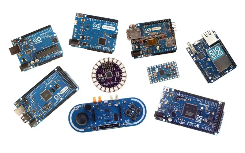
While initially built around AVR microcontrollers, the open-source nature of the platform has led the community to port the Arduino core to powerful ARM-based chips and beyond. Today, "Arduino" refers not just to a single piece of hardware, but to a comprehensive, ever-expanding ecosystem of development boards and software platforms.
At its core, Arduino is an open-source platform governed by Creative Commons licenses. This means its hardware schematics, PCB layouts, and software source code are freely available for anyone to use, modify, and distribute—empowering users to even manufacture their own custom Arduino-compatible boards.
The platform essentially serves as a highly refined microcontroller interface. It provides ready-to-use capabilities for data processing, timers, serial and bus communication, PWM signal generation, and analog-to-digital (A/D) conversion. By enabling developers to manipulate electrical signals and interface with sensors through straightforward programming, Arduino lowers the barrier to entry for electronics design. It bridges the gap between software and hardware, allowing creators to focus on the "smart" logic of their projects rather than getting bogged down by intricate circuit theory.
As the platform has grown, so has its hardware ecosystem. The market is flooded with stackable expansion shields and compatible modules, standardizing features like wireless communication, environmental sensing, and motor control. Furthermore, its native serial communication makes it seamless to interface with desktop software like Processing, LabVIEW, Max/MSP, and VVVV for interactive installations.
Most Arduino boards are highly adaptable, supporting DC power supplies ranging from 5V to 12V (with some operating at 3.3V). During debugging, the board can be safely powered directly via USB, eliminating the need for external power supplies.
Summary of Core Advantages:
| Technical Specification | Arduino Uno R3 | Arduino Mega2560 Rev3 | Arduino Leonardo |
|---|---|---|---|
| Microcontroller | ATmega328 | ATmega2560 | ATmega32u4 |
| Operating Voltage | 5V | 5V | 5V |
| Input Voltage (Recommended) | 7-12V | 7-12V | 6-20V (Range) |
| Input Voltage (Limits) | 6-20V | 6-20V | Not explicitly marked |
| Digital I/O Pins | 14 (6 provide PWM output) | 54 (15 provide PWM output) | 20 (7 provide PWM output) |
| Analog Input Pins | 6 | 16 | 12 |
| DC Current per I/O Pin | 40 mA | 40 mA | 40 mA |
| DC Current for 3.3V Pin | 50 mA | 50 mA | 50 mA |
| Flash Memory | 32 KB (0.5 KB used by bootloader) | 256 KB (8 KB used by bootloader) | 32 KB (4 KB used by bootloader) |
| SRAM | 2 KB | 8 KB | 2.5 KB |
| EEPROM | 1 KB | 4 KB | 1 KB |
| Clock Speed | 16 MHz | 16 MHz | 16 MHz |
| Dimensions | 75 x 55 x 15 mm | Not Specified | 70 x 55 x 14 mm |
| Weight | Not Specified | Not Specified | Approx. 20g |
| Package Contents | 1x Arduino Uno R3 (Original) | 1x Arduino Mega2560 Rev3 (Original) | 1x Arduino Leonardo |
Designing an Arduino PCB from scratch doesn't have to be overwhelming. Follow these steps to go from schematic to a board ready for manufacturing.
Before opening any PCB design software, answer these questions:
Defining requirements upfront prevents costly redesigns later.
Use a tool like KiCad or EasyEDA to draw your schematic first. Add:
Pro tip: Reference the official Arduino Uno schematic as a starting point — it's open-source and freely available.
Every component in your schematic needs a physical footprint. Key rules:
Define your PCB boundary (Edge.Cuts layer in KiCad). Common Arduino form factors:
Component placement is the most critical phase. Follow this priority order:
Key routing rules for Arduino PCBs:
Before exporting, always run DRC to catch:
Fix all errors before generating output files.
Even experienced designers make these mistakes. Check each one before sending your files to a manufacturer.
Every VCC pin on your MCU and ICs needs a 100nF decoupling capacitor placed as close as possible to the pin. Missing these causes erratic behavior, resets, and noise issues.
Fix: Add a 100nF capacitor for each VCC pin, plus a bulk 10µF capacitor near the power input.
The Arduino's clock circuit is sensitive. Common errors:
Fix: Place the crystal and its load caps within 5mm of the MCU's XTAL pins. Route these traces short and straight.
If the RESET pin isn't properly pulled high, your Arduino will reset randomly.
Fix: Always connect a 10kΩ resistor from RESET to VCC. Add a 100nF capacitor to ground for noise immunity.
Thin traces on power rails cause voltage drops and overheating.
Fix: Use the IPC-2221 trace width calculator. For 500mA, use at least 0.8mm width on external layers.
A board without component references and polarity markers is impossible to assemble or debug.
Fix: Add silkscreen designators for every component. Mark polarity on diodes, electrolytic capacitors, and polarized connectors.
If your design has trace widths below 0.1mm or drill holes under 0.2mm, many manufacturers cannot produce it reliably.
Fix: Design to standard manufacturing tolerances (0.15mm trace/space minimum, 0.3mm minimum drill) unless you specifically need advanced capabilities.
Traces too close to the board edge can be cut during routing.
Fix: Keep all copper at least 0.3mm (ideally 0.5mm) from the board edge.
Gerber files are the universal format PCB manufacturers use to produce your board. Here's how to export them correctly from the two most popular free tools.
KiCad 10, released in early 2026, introduced a streamlined Fabrication Outputs workflow that simplifies Gerber export significantly compared to older versions.
.zip archiveWhat's new in KiCad 10: The redesigned Design Rules Check (DRC) engine now flags manufacturability issues directly in the PCB editor before you export — look for the DRC panel warnings under Inspect → Design Rules Checker. Fixing these upstream means fewer surprises when the manufacturer reviews your files.
Tip: NEXTPCB accepts KiCad 10's default Gerber output without any manual adjustments.
.zip fileEasyEDA also lets you click "Order at JLCPCB/NEXTPCB" directly, but manually reviewing the Gerber preview before ordering is always recommended.
Before uploading to any manufacturer, verify your files using a free Gerber viewer:
Check that all layers look correct and the board outline is complete before placing your order.
Once your Gerber files are ready, here's what you need to understand about the manufacturing process.
When you place an order, you'll be asked to specify:
| Parameter | Typical Value for Arduino Projects |
|---|---|
| Layers | 2 (most projects) |
| Board thickness | 1.6mm (standard) |
| Copper weight | 1oz (35µm) |
| Surface finish | HASL (most affordable) or ENIG (better for fine-pitch SMD) |
| Solder mask color | Green (fastest), Black, Blue, Red, White |
| Silkscreen | White (standard) |
| Min trace/space | 0.15mm/0.15mm |
| Min drill size | 0.3mm |
For an Arduino project, you typically start with a prototype run:
NEXTPCB offers 5pcs 2-layer boards at very competitive prototype pricing, making it easy to iterate quickly without large upfront costs.
If you don't want to hand-solder your boards, NEXTPCB also offers SMT assembly services:
For an Arduino prototype with mostly through-hole components, hand soldering is usually sufficient. For all-SMD designs, PCBA saves significant time.
| Service | Turnaround |
|---|---|
| Standard prototype | 5–7 business days |
| Express prototype | 24–48 hours |
| Standard production | 7–15 business days |
For urgent projects, NEXTPCB's 24-hour express service ensures you receive boards in the shortest possible time.
>> Arduino Development:
Does Arduino Uno Have Bluetooth? Exploring Connectivity Options
Arduino Speaker Projects: Make Your Own Music
Arduino Uno vs. Mega vs. Micro: Main Differences - NextPCB
With dozens of PCB manufacturers available online, here's why NEXTPCB is a strong choice for Arduino designers and makers.
NEXTPCB offers affordable pricing for small-quantity prototype runs — ideal for hobbyists, students, and startups who need to iterate quickly without large budgets.
Standard prototypes ship in 24–72 hours. For time-sensitive projects or hackathons, the express service ensures your boards arrive when you need them.
Before manufacturing begins, NEXTPCB performs a Design for Manufacturability (DFM) check on your Gerber files. This catches issues like:
This free review prevents manufacturing defects before they happen.
NEXTPCB's online ordering system provides an instant quote as soon as you upload your Gerber files. No waiting for manual quotes — you see the price immediately and can adjust specifications to fit your budget.
NEXTPCB handles both bare board fabrication and SMT/through-hole assembly. This means you can order fully assembled Arduino boards — components soldered and ready to test — from a single supplier.
NEXTPCB manufactures to IPC Class 2 standards as a baseline, with IPC Class 3 available for demanding applications. Every batch undergoes:
The order portal supports direct Gerber ZIP upload, real-time order tracking, and repeat order functionality — making it simple to reorder your Arduino PCB as your project scales.
Not necessarily. PCB design and firmware development are separate skills. You can design the hardware first — the schematic and PCB layout — without writing a single line of code. Many designers sketch the circuit in KiCad or EasyEDA, get prototypes made, and write firmware in parallel. That said, having a basic understanding of how your code uses the hardware (which pins do what, what voltage levels are expected) helps you avoid layout mistakes early.
This is more common than you'd think, especially on a first spin. Start systematically:
Don't panic if rev1 doesn't work. Most hardware engineers budget for at least two prototype iterations.
Yes. The Arduino hardware designs are open-source (Creative Commons license), but selling a product that calls itself "Arduino" requires a license from Arduino LLC. However, making a custom board based on the same MCU and circuit without the Arduino branding is perfectly legal. Many successful products are built this way — just swap the ATmega for your preferred chip and build your own firmware.
Most online PCB manufacturers, including NEXTPCB, offer prototype runs starting at 5 pieces. This is ideal for first-time orders — you get enough boards to test, debug, and share with collaborators without committing to large quantities.
For a standard 2-layer board (roughly Arduino Uno size, 100mm × 80mm), prototype pricing typically falls in the range of $5–$30 for 5–10 boards, depending on specifications and turnaround time. Surface finish, solder mask color, and express options affect the final price. Use any manufacturer's instant quote tool to get an exact number before committing.
Both are free and capable. The honest answer:
Start with EasyEDA if you want fast results. Move to KiCad when your projects get more complex.
No. For bare board fabrication (no assembly), you only need your Gerber files and drill files. A BOM is only required if you're also ordering PCB assembly (PCBA) — where the manufacturer sources and solders the components for you.
Reputable manufacturers perform a DFM (Design for Manufacturability) check on your files before production starts. If they find a problem — a missing board outline, a trace too close to a via, or an unsupported drill size — they'll contact you to confirm before proceeding. This is normal, not a red flag. It's actually a good sign that the manufacturer is doing their job properly.
Custom PCB design for Arduino projects has never been more approachable. The tools are free, the community knowledge base is enormous, and manufacturing services have made prototyping affordable for everyone from students to startups.
The main thing that separates a successful first PCB from a frustrating one is methodical execution: solid schematic, careful placement, clean routing, thorough DRC, and proper Gerber export. None of these steps are particularly hard — they just require attention.
If you've worked through this guide and you're ready to see your design as a real physical board:
Upload Your Gerber Files & Get an Instant Quote → Free DFM review on every order.
Still, need help? Contact Us: support@nextpcb.com
Need a PCB or PCBA quote? Quote now


 Surface

