
 NextPCB Capabilities
Printed Circuit Boards
NextPCB Capabilities
Printed Circuit Boards
 PCB Assembly
 Layer Buildup
 SMD-Stencils
 PCB Design-Aid & Layout
 Mechanics
 Quality
 Drills & Throughplating
 Factory & Certificate
 PCB Assembly Factory Show
Certificate
PCB Assembly Factory Show
Certificate
Support Team
Feedback:
support@nextpcb.com


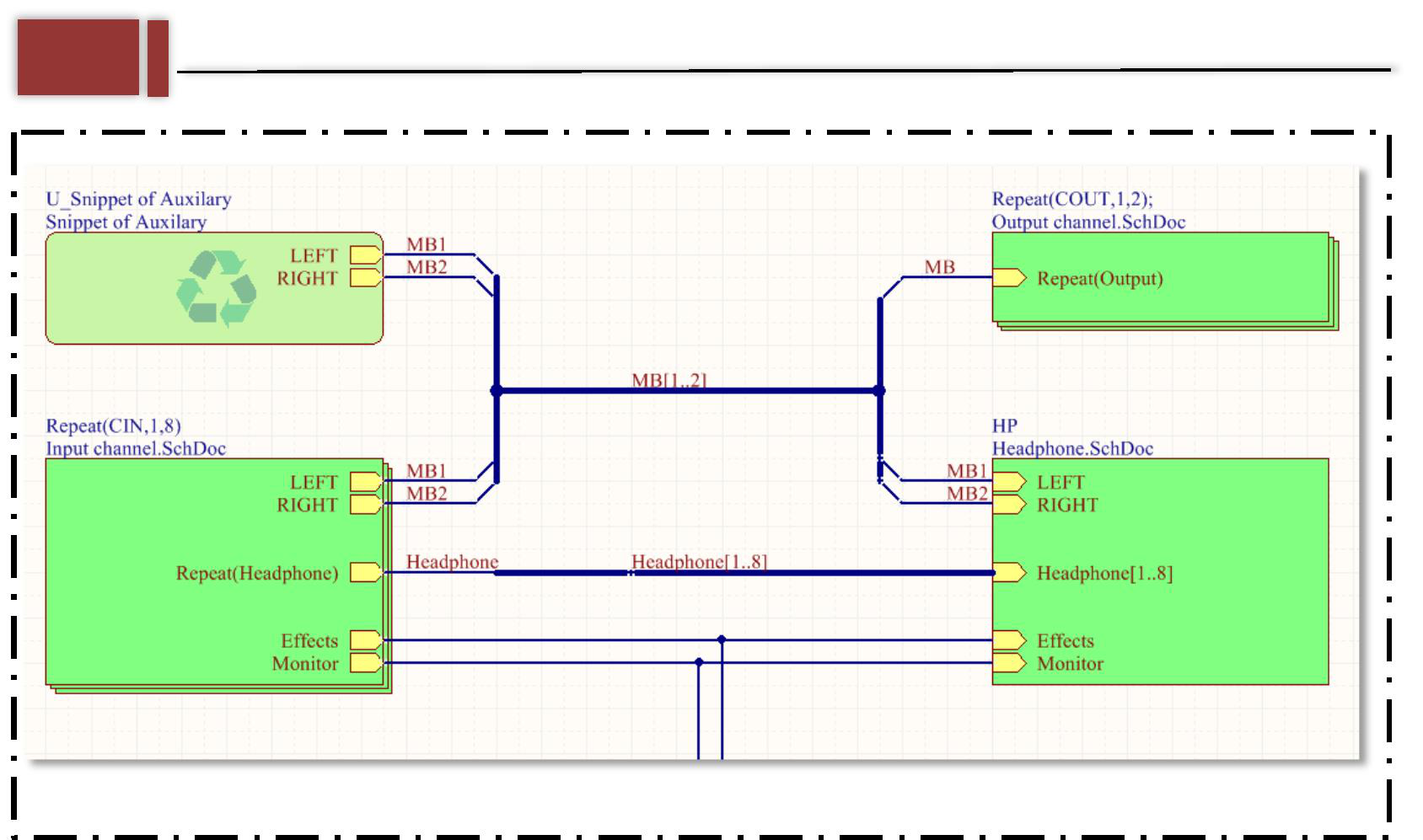
When using Altium Designer for schematic drawing, if you use a top-down design approach, the entire schematic will be divided into many sub-modules. There are many modules that are used on almost every board, so in order to facilitate the reuse of modules in the schematic design for timing, we use device graph symbols and Snippets. In this way, when drawing the schematic diagram only once, if you need to insert it directly from the device diagram symbol library, the following briefly introduces how to use these two functions.
[Related Discussion Posts]
[1] Altium Designer 9.0 snippets (module reuse)
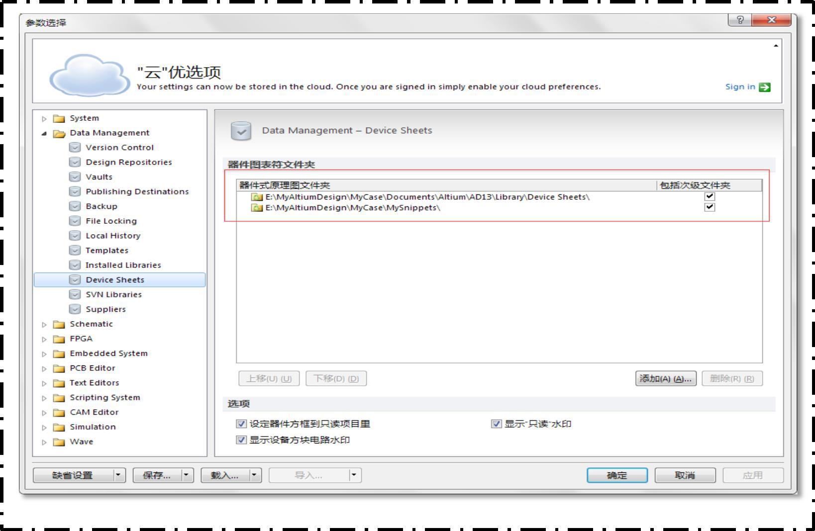
The previous tutorial introduced how to use Sheet Symbol for multi-channel design, then the device chart symbol is equivalent to reusable
Sheet Symbol. The equipment diagram symbol can abstract the drawing into a module and put it directly on the schematic diagram for use; we can create a new folder to store equipment drawings. As shown in the figure below, set the library for storing device graph symbols in the parameter selection.
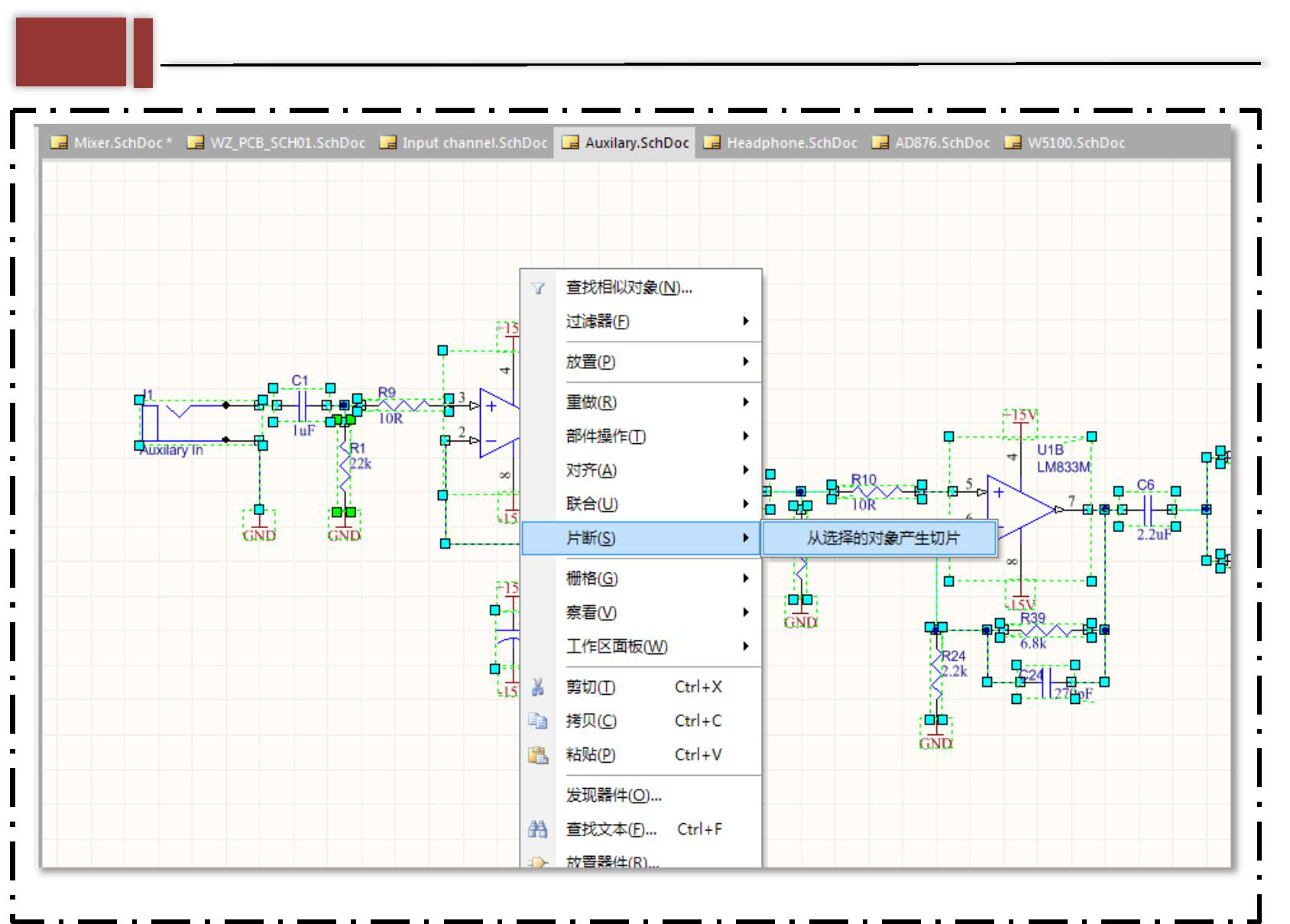
Altium designer software provides us with a part of the device chart characters to use. If we want to make a module drawing to be used frequently as a device chart character, we need to use snippet, select the circuit to generate the device chart character on the schematic page, and right-click to generate the slice from the selected object. As shown in the figure below, the device diagram is generated.
Then set the name, storage address and description of the device icon in the pop-up page.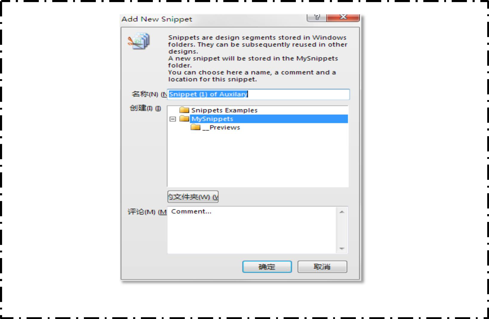
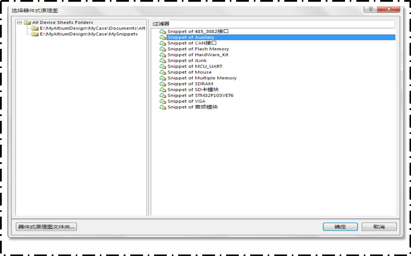
Place the reused device diagram symbol in the project, and select the device icon you want to place.
Please refer to the official documents for specific operations.
Still, need help? Contact Us: support@nextpcb.com
Need a PCB or PCBA quote? Quote now


 Surface

