
 NextPCB Capabilities
Printed Circuit Boards
NextPCB Capabilities
Printed Circuit Boards
 PCB Assembly
 Layer Buildup
 SMD-Stencils
 PCB Design-Aid & Layout
 Mechanics
 Quality
 Drills & Throughplating
 Factory & Certificate
 PCB Assembly Factory Show
Certificate
PCB Assembly Factory Show
Certificate
Support Team
Feedback:
support@nextpcb.com


I have been using Altium Designer for more than a year. When I first started learning, I used a flat design method when drawing schematics. In this way, it’s okay if the schematic is simple, but if it’s complicated, all the circuit diagrams are on a piece of paper and it looks a bit different.
Convenient and easy to make mistakes. And there are many modular circuits that have to be pasted from the schematics drawn before, which is very troublesome. After looking at the help file that comes with the software, I found a design method that is multi-drawing and multi-channel design. The point to be explained here is that most of the design methods in this series of tutorials are learned by learning the help files of the software. In fact, the person who designed AltiumDesigner must know this software very well, so if you learn to use a software, In fact, you can learn how to use the software by carefully reading the software's built-in help files. There is no need to learn software for the sake of learning software, it is just a tool
That's it. As for the flat design method or the hierarchical design method, which one is better, I don't want to say anything more here, but according to the needs of the project, just use the best method you feel to complete the schematic design.
[Related Discussion Posts]
[1] Use the hierarchical chart correctly, you will find that ORCAD/PADS/CADENCE is weaker than AD
[2] Hierarchical schematic or flat schematic
[3] "It is enjoyable to draw schematics in AD", which is stronger than the schematics of Altium and OrCAD?
The design of multiple drawings is completed by placing a sheet symbol in the top-level schematic, as shown in the figure below.
Place Sheet Symbol in Altium designer. A chart symbol can generate a drawing;
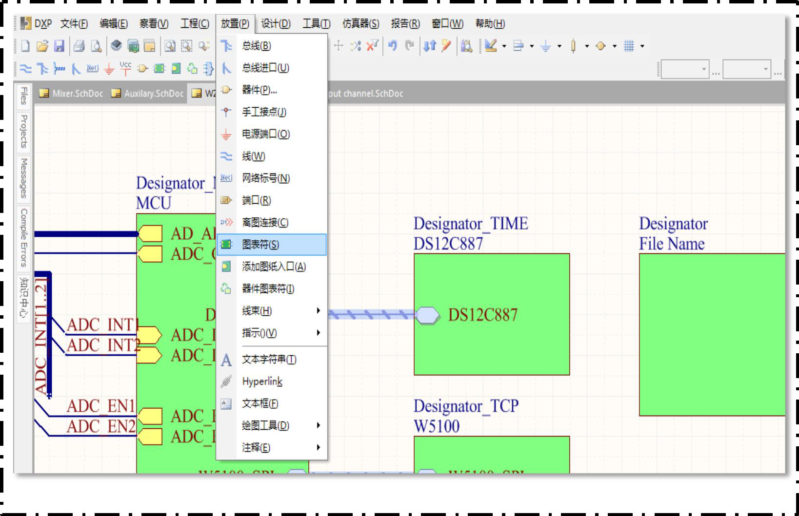
Here to explain, there are two methods for multi-drawing design hierarchy:
[1] From top to bottom: In the top-level schematic diagram, sub-drawings are generated through Sheet Symbol:
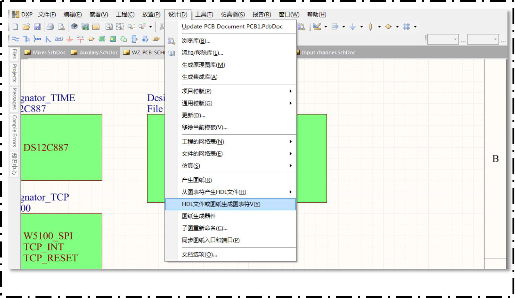
[2] Bottom-up: Generate chart symbols through drawings in the top-level schematic;
Choose to generate chart symbols from drawings:
"Designator" is the identifier, and the repeat keyword is used for the multi-channel design in the following text; "File Name" is the sub-drawing file name.
After selection, the inlets and ports of the synchronized sub-drawings will be automatically placed in the top-level schematic drawing.
1) Only the steps of the top-down design method are introduced here. In the top-level schematic, sub-drawings are generated through Sheet Symbol
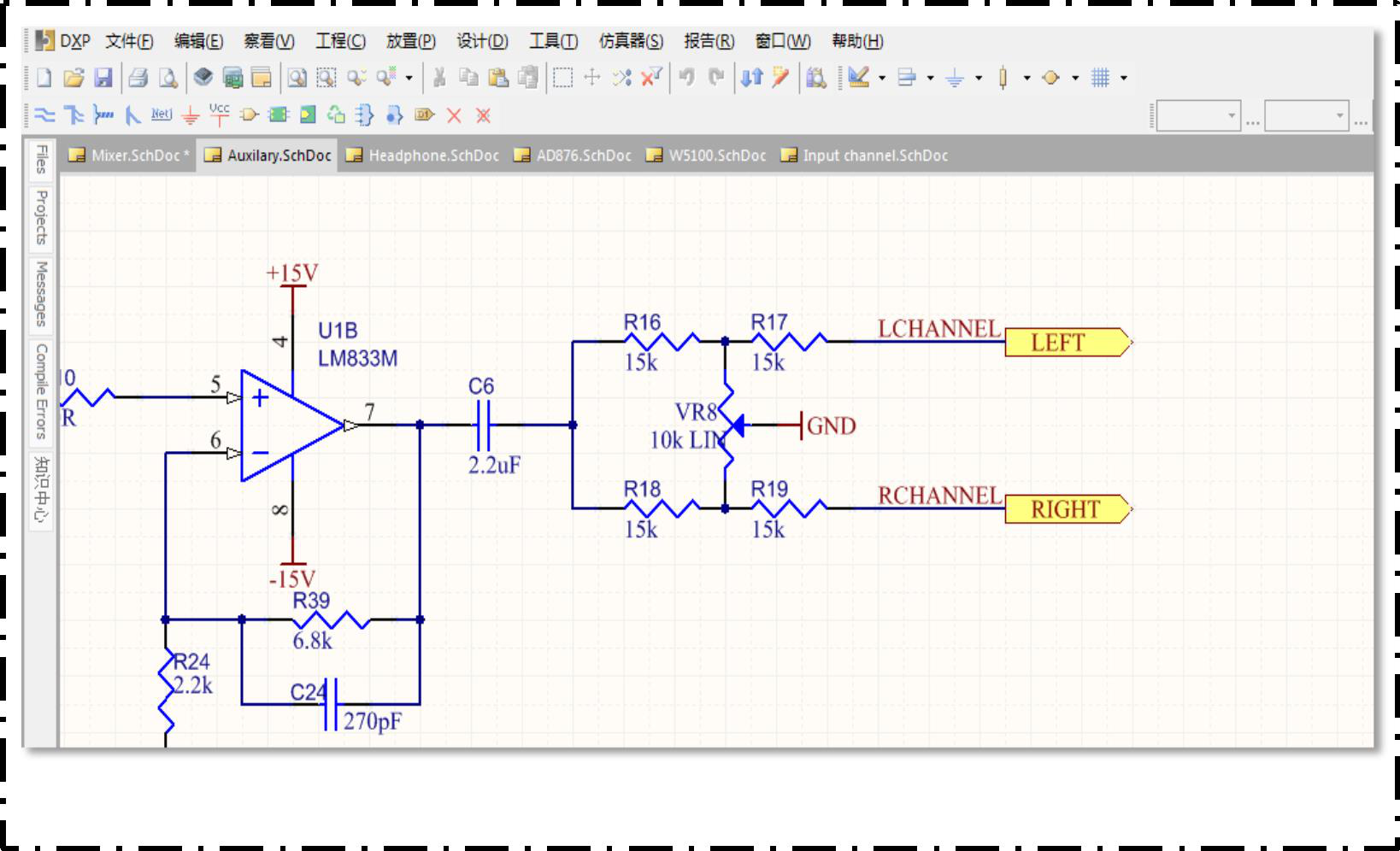
Then, draw the schematic diagram in the sub-drawing of the corresponding module, and place the port under the menu).
To connect with the network connected to other modules, as shown in the figure below.
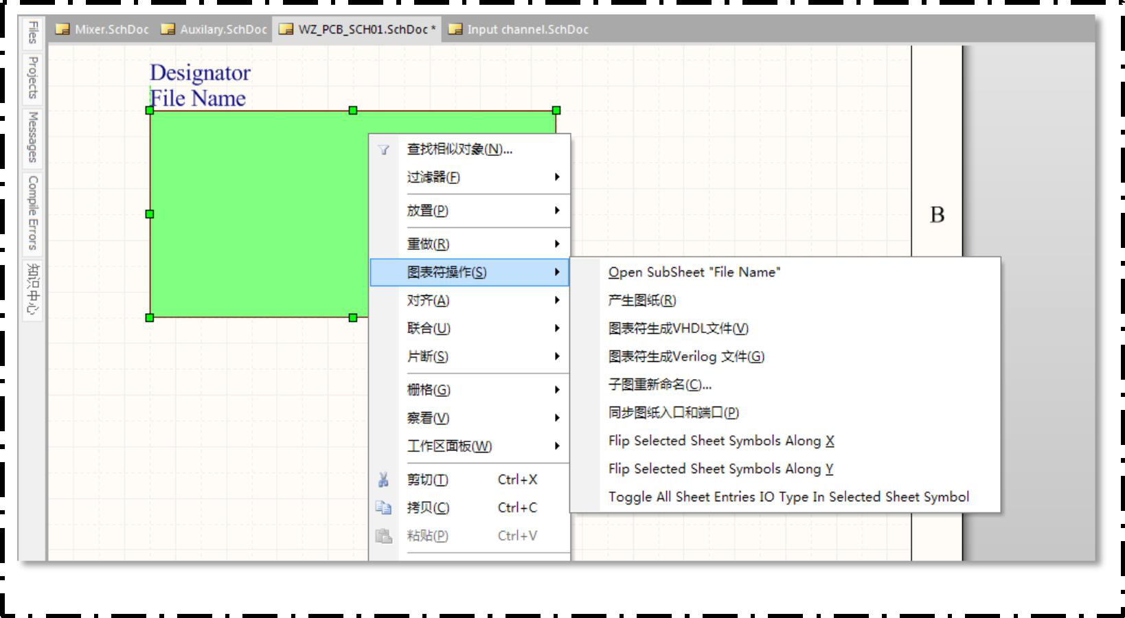
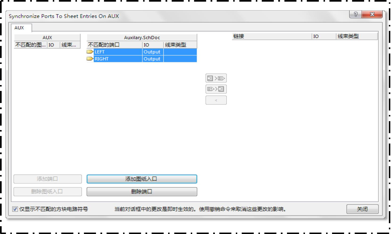
2) After completing the schematic drawing of the sub-drawing, in the top-level schematic drawing, right-click the corresponding diagram symbol to synchronize the sub-drawing entrance and port, As shown below.
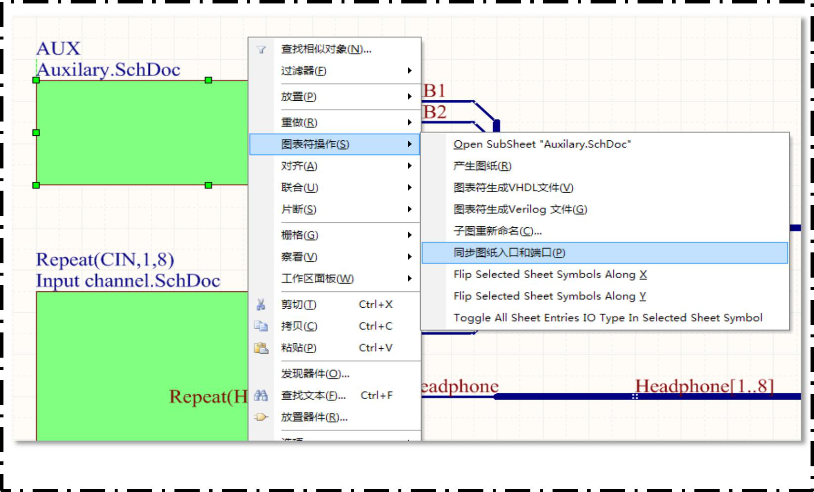
Select the sub-drawing entry and port to be synchronized
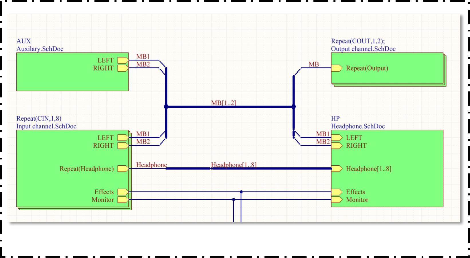
3) Complete the drawing of the schematic diagram of each sub-module in the same way, and complete the synchronization of the drawing entrance and port. According to the electrical connection of the schematic diagram Connect to connect.
[Note] Switch between the top-level schematic and sub-drawings through the upper and lower switching tools.
The multi-channel design in the engineering schematic diagram is to facilitate the reuse of a certain module, for example, if a multi-channel AD acquisition module
, If the circuit of each acquisition channel is the same, then it is not necessary to draw the schematic diagram of each channel, just draw the
One schematic diagram, and then use a multi-channel design method to generate multiple AD acquisition channels. This can reduce repetitive work on the one hand, On the other hand, after drawing the schematic diagram in a multi-channel way, the layout and routing of the ROOM can be easily copied in the PCB Layout.
If the layout of each acquisition circuit is also the same, as long as the layout and wiring of one channel are completed first, the others can be directly entered.
Just copy it (how to use it will be described in detail later).
1) Use the Repeat keyword to generate multiple channels after completing the drawing of the single-channel Sheet Symbol and the schematic diagram of the sub-figure according to the above tutorial
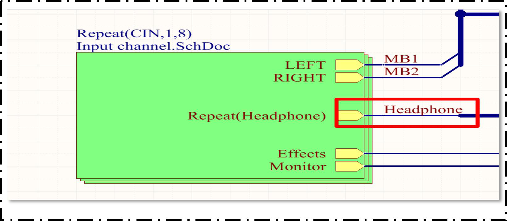
As shown in the figure above, the Repeat keyword is used to name the identifier. The naming rule: Repeat (chart symbol name, first channel number, last
The latter is numbered). In the picture just now, there are 8 Sheet Symbols of the same channel. The number of each channel is 1, and the last one is
The number of the road is 8. 8 Headphone ports can be generated through Repeat (Headphone), respectively
Headphone1~Headphone8. The single-line Net marked by the red line in the figure must be connected to the bus by placing the NetLabel.
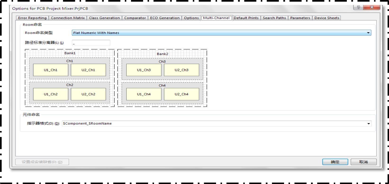
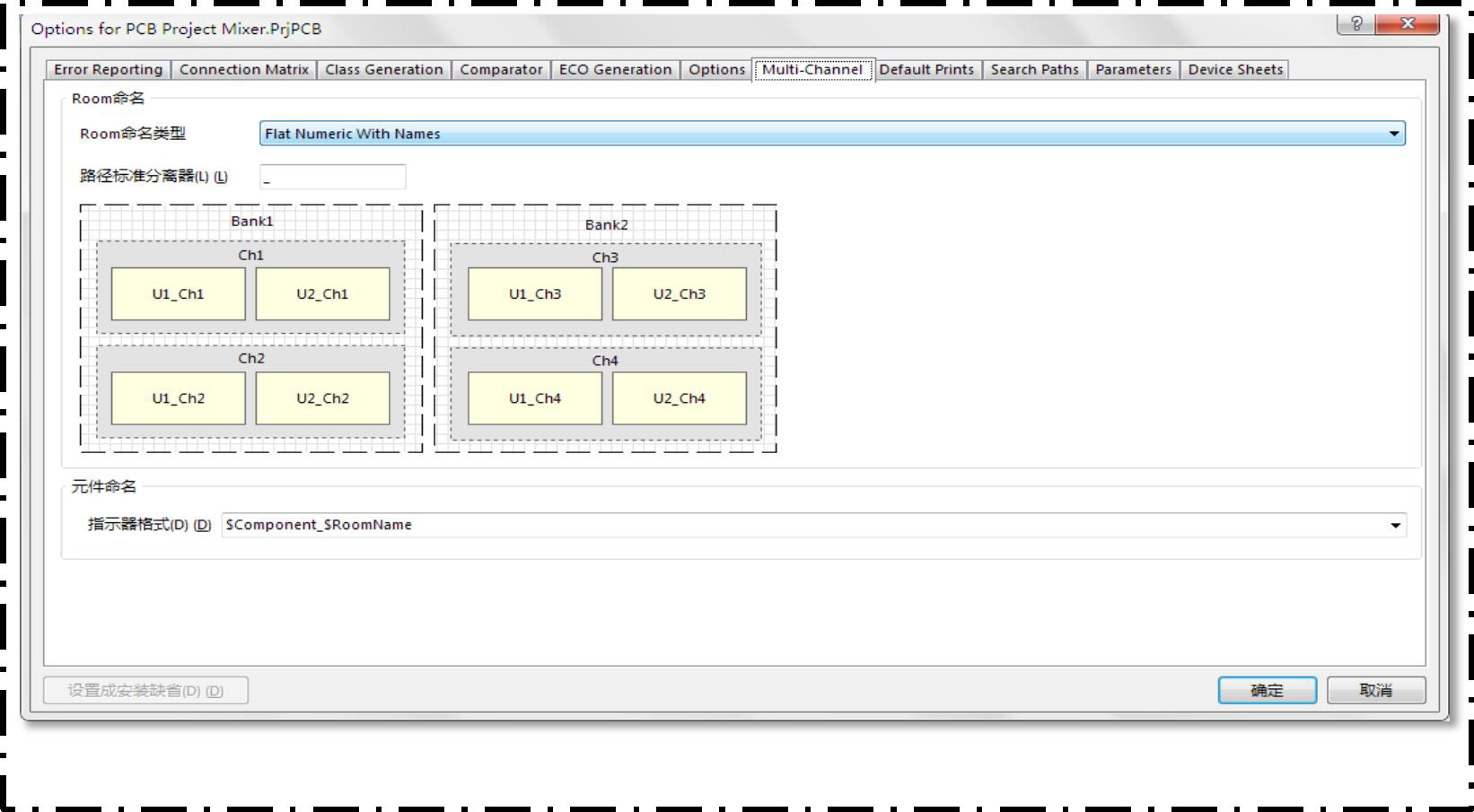
After completing the multi-channel schematic drawing, the naming method of the channels and components should be set. Click "Project -> Project Parameters",
Click on the "Multi-Channel" tab in the dialog box to make the settings as shown in the figure below.
Click "Project -> View Pipeline" to view each schematic diagram and the distribution of component identifiers in each channel, as shown in the figure below
Show.
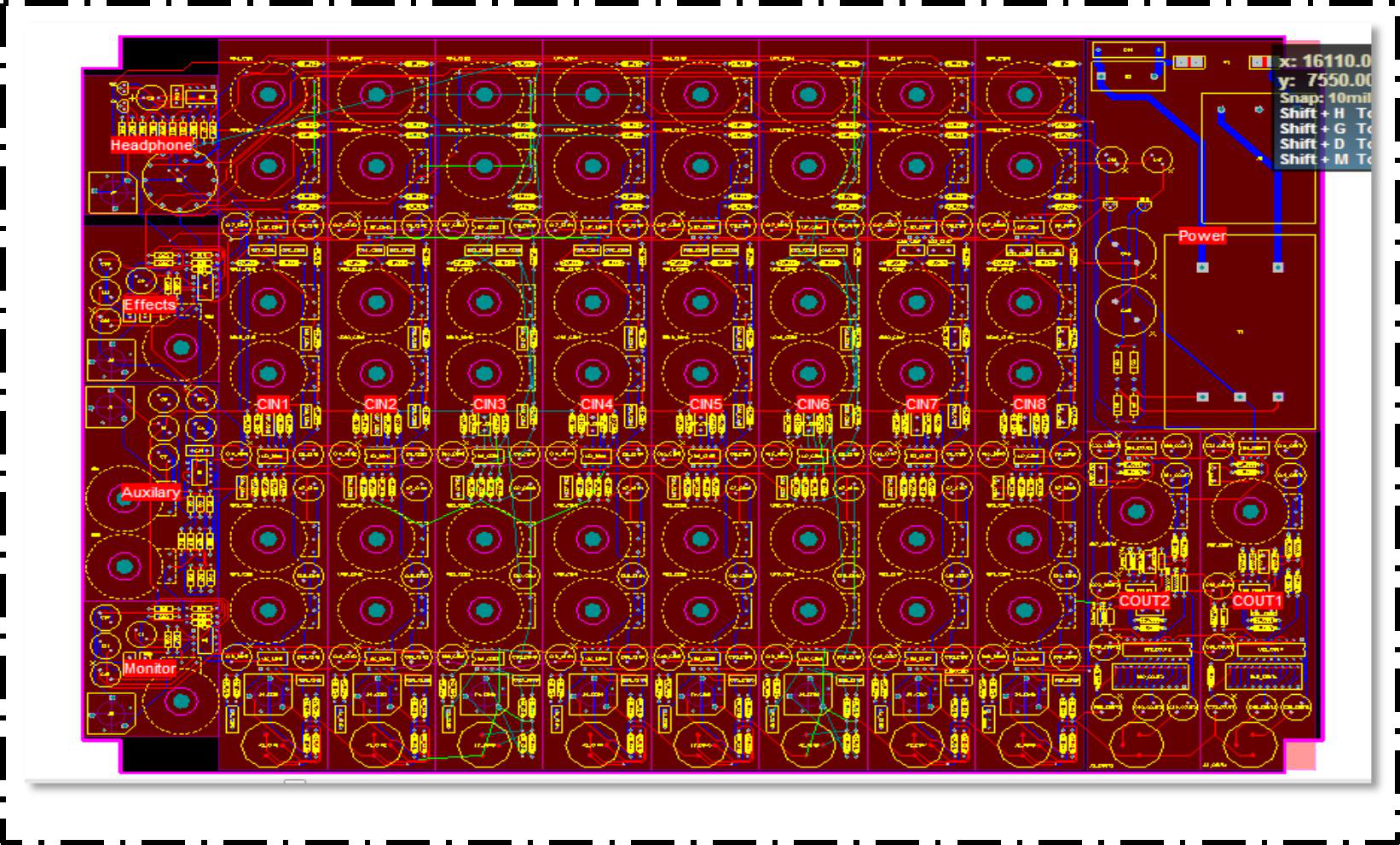
If the layout of each module circuit designed by multi-channel is the same on the PCB board, then only the layout and layout of one of the channels needs to be completed.
Lines can be used to copy ROOM to complete the layout and routing of other channels.
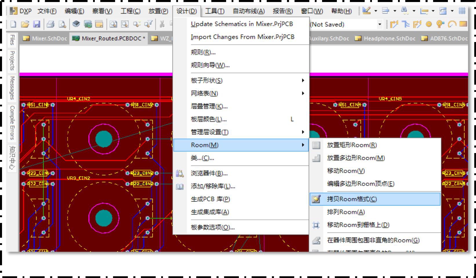
Then click the ROOM where the layout and routing have been completed and the ROOM where the same layout and routing are to be performed. In the same way, the layout and wiring of the remaining channels are completed.
Still, need help? Contact Us: support@nextpcb.com
Need a PCB or PCBA quote? Quote now


 Surface


inel
Great page of Altium hierarchical design course.
Anonymous18
Detailed Altium Designer design tutorial! Good!